9921-FS-OM (V1.18)
9921-FS PRODUCT MANUAL
1-19
Introduction
9921-FS Functional Description
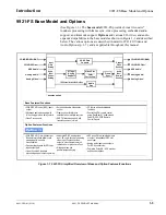
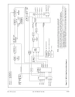
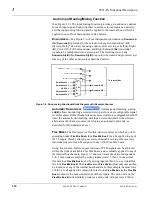
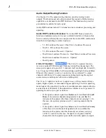
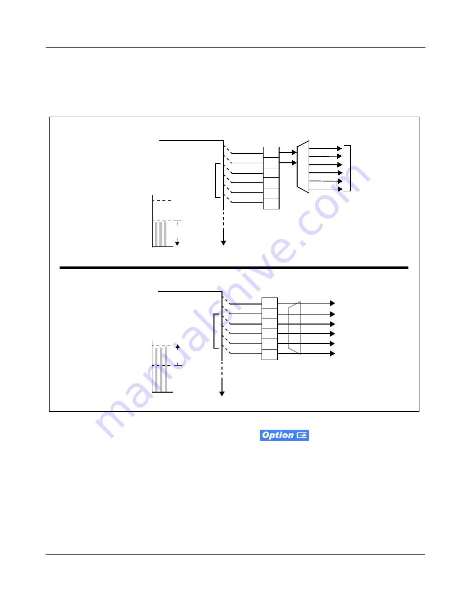
The examples in Figure 1-8 show the automatic enable/disable upmixing
function applied to example selected channels
Bus Ch 1
thru
Bus Ch 6
. As
shown and described, the processing is contingent upon the signal levels of
the channels selected to carry the new 5.1 upmix relative to the selected
threshold (in this example, -60 dBFS).
Figure 1-8 Upmixing Auto Enable/Bypass with Example Sources
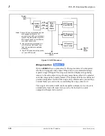
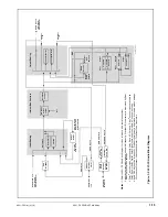
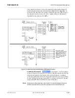
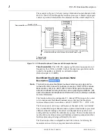
Loudness Processor.
(See Figure 1-9.) The loudness
processor function receives up to six selected channels from the internal bus
and performs loudness processing on the selected channels. A loudness
processing profile best suited for the program material can be selected from
several loudness processing presets. Refer to catalog or Fusion3G
®
manual
supplement OPT-SW-F3GLP-MS for more information.
Note:
Discussion and example here describes 5.1-channel loudness processor.
Stereo and dual-stereo processors operate similar to described here.
Bus Ch 1 – Ch 16
>
From
Internal
Bus
Bus Ch 1
Bus Ch 2
Bus Ch 3
Bus Ch 4
Bus Ch 5
Bus Ch 6
L
R
(C)
(LFE)
(Ls)
(Rs)
With all detected signal levels on
Bus Ch 3, 5 and 6 below
threshold, upmixer is active and
generates new 5.1 content.
Threshold
Detect
5.1 Upmix
Bus Ch 1 – Ch 16
>
Bus Ch 1
Bus Ch 2
Bus Ch 3
Bus Ch 4
Bus Ch 5
Bus Ch 6
L
R
(C)
(LFE)
(Ls)
(Rs)
Threshold
Detect
Because the selected
channels are already carrying
viable content, upmixing is
bypassed, allowing the six
original Bus Ch 1 – Ch 6 to
pass through upmix outputs
Upmix L thru Upmix Rs
unmodified.
With any detected signal levels
on Bus Ch 3, 5 or 6 above
threshold, upmixer is bypassed.
- 20 dBFS
- 60 dBFS
Above Threshold
(Bypass)
C Ls Rs
- 20 dBFS
- 60 dBFS
Below Threshold
(Overwrite)
C Ls Rs
From
Internal
Bus
Upmix L
Upmix R
Upmix C
LFE
Upmix Ls
Upmix Rs
Upmix outputs
consist of new
upmix content

