2
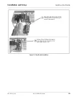
Installing the 9921-FS Into a Frame Slot
2-2
9921-FS PRODUCT MANUAL
9921-FS-OM (V1.18)
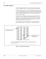
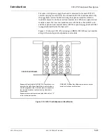
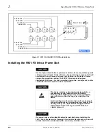
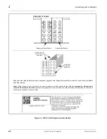
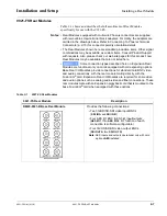
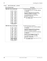
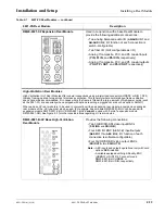
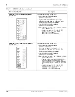
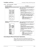
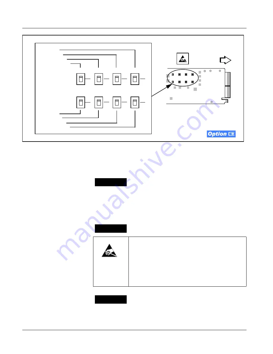
Figure 2-1 9921-FS AN-AUD I/O (1-8) Mode Switches
Installing the 9921-FS Into a Frame Slot
CAUTION
Heat and power distribution requirements within a frame may dictate specific
slot placement of cards. Cards with many heat-producing components should
be arranged to avoid areas of excess heat build-up, particularly in frames
using only convection cooling. The 9921-FS has a moderate power
dissipation (20 W max.). As such, avoiding placing the card adjacent to other
cards with similar dissipation values if possible.
CAUTION
CAUTION
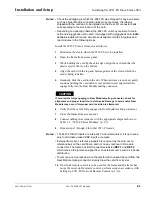
If required, make certain Rear Module(s) is installed before installing the
9921-FS into the frame slot. Damage to card and/or Rear Module can occur if
module installation is attempted with card already installed in slot.
Rear of Card
AN-AUD I/O 1
AN-AUD I/O 2
AN-AUD I/O 3
AN-AUD I/O 4
S1
S2
S3
S4
IN
OUT
IN
OUT
IN
OUT
IN
OUT
S5
S6
S7
S8
IN
OUT
IN
OUT
IN
OUT
IN
OUT
AN-AUD I/O 8
AN-AUD I/O 7
AN-AUD I/O 6
AN-AUD I/O 5
This device contains semiconductor devices which are
susceptible to serious damage from Electrostatic
Discharge (ESD). ESD damage may not be immediately
apparent and can affect the long-term reliability of the
device.
Avoid handling circuit boards in high static environments
such as carpeted areas, and when wearing synthetic fiber
clothing. Always use proper ESD handling precautions
and equipment when working on circuit boards and
related equipment.

