background image

9921-FS-OM  (V1.18)

9921-FS PRODUCT MANUAL

2-11

Installation and Setup

Installing a Rear Module

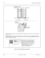
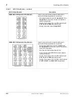
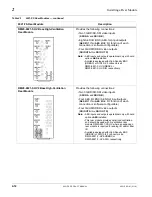
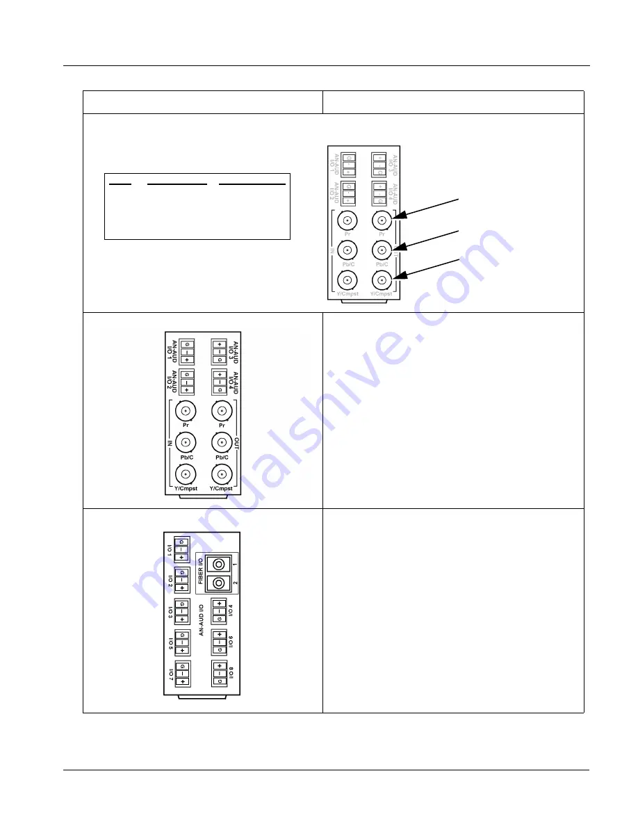
Note: When using Y/C (“S-video”) analog input or output, connections are as shown below and not as shown on label 

(which correspond to YPbPr and composite mode connections).

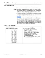
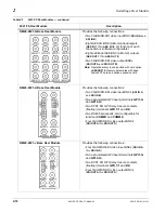
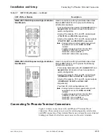
RM20-9921-XB Expansion Rear Module

Used in conjunction with a base Rear Module to 
provide the following additional connections:

• Four analog balanced audio I/O (

AN-AUD I/O 1

 thru 

AN-AUD I/O 4

; I/O function of each connection is 

switch-configurable)

• Analog Y/composite, Pr/C, and Pb coaxial inputs

(Y INPr IN, and Pb/C IN, respectively) 

• Analog Y/composite, Pr/C, and Pb coaxial outputs

(Y OUTPr OUT, and Pb/C OUT, respectively)

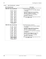
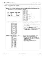
RM20-9921-XC Expansion Rear Module

Used in conjunction with a base Rear Module to 
provide the following additional connections:

• Eight analog balanced audio I/O (

AN-AUD I/O 1


thru 

AN-AUD I/O 8

; I/O function of each connection 

is switch-configurable)

• Two fiber I/O (GUI configurable as I/O)

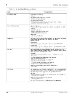
Table 2-1

9921-FS Rear Modules — continued

9921-FS Rear Module

Description

Label

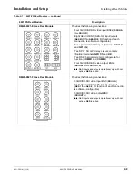
Y/C Input Mode

Y/C Output Mode

Pr

C

C

Pb/C

Y

Y

Y/Cmpst

NC

Composite

C

Y

See table

Summary of Contents for 3G Fusion 9921-FS

Page 1: ...9921 FS 2506 Galen Drive Champaign IL 61821 Voice 217 344 1243 Fax 217 344 1245 www cobaltdigital com Product Manual 9921 FS OM V1 18 Cobalt Digital Inc 3G HD SD SDI Frame Sync...

Page 2: ...this card is manufactured under license from Dolby Laboratories Dolby is a registered trademark of Dolby Laboratories Inc Other product names or trademarks appearing in this manual are the property of...

Page 3: ...n 1 8 Audio Subsection Description 1 13 Control and Data Input Output Interfaces 1 21 User Control Interface 1 22 9921 FS Rear Modules 1 24 Audio and Video Formats Supported by the 9921 FS 1 26 Techni...

Page 4: ...Menu List and Descriptions 3 10 Video Input Control 3 11 Video Proc Color Correction 3 11 Timecode 3 15 Closed Captioning 3 19 Framesync 3 21 AFD WSS VI ARC Controls 3 24 Video Output Crosspoint Cont...

Page 5: ...ing the 9921 FS Chapter 2 Installation and Setup Provides instructions for installing the 9921 FS in a frame and optionally installing 9921 FS Rear Modules Chapter 3 Operating Instructions Provides ov...

Page 6: ...guides covering network remote control card firmware updates example card processing UI setups and other topics Card Software earlier than latest version Card is not loaded with the latest software No...

Page 7: ...nd terminal equipment in which the 9921 FS and other COMPASS and or FUSION3G cards operate Functions and or features that are available only as an option are denoted in this manual like this Not all o...

Page 8: ...appropriate video terminal equipment operating environments CAUTION This product is intended to be a component product of an openGear frame Refer to the openGear frame Owner s Manual for important saf...

Page 9: ...ormats GPI ports with user definable functions Centralized GUI remote control using DashBoard software and Cobalt OGCP 9000 Remote Control Panels Option Features Functions 3G HD SD SDI Fiber input out...

Page 10: ...x 1 Fiber input Option FRx Tx 1 Fiber input 1 Fiber output Option FRx Rx 2 Fiber inputs Requires Expansion Rear Module supporting fiber I O See 9921 FS Rear Modules p 2 7 for more information AES Audi...

Page 11: ...iption and signal connection information Keying Provides keying using independent SDI inputs for key and fill signals Also provides a separate dedicated key preview SDI output Refer to option Manual S...

Page 12: ...Various controls can be ganged to provide adjustment for all three color channels simultaneously The color correction function can be user selected to be applied to input video or output video as sho...

Page 13: ...This function uses extracted Aspect Ratio Control ARC data from the input video in either AFD WSS or VI formats and provides Format translation between AFD WSS and VI ARC formats H V cross conversion...

Page 14: ...e controlling the wings video feed The wings L R insertion width can be manually configured or can be set to automatically track with aspect ratio as set by the host card on cards equipped with aspect...

Page 15: ...ber Tx Tx A Tx B FIBER Tx A OUT FIBER Tx B OUT Serialize NOTE 4 Relay Bypass NOTE 6 Timecode and Closed Captioning Processors TC CC ANC Data In TC CC ANC Data Out Network Remote Control Ethernet 10 10...

Page 16: ...on also provides conversion between various timecode formats and provides independent insertion and line number controls for each SDI timecode output format When licensed with option LTC this function...

Page 17: ...put SDI OUT A Audio Subsection Description Note Descriptions below include some functions and features that are available only as options See Figure 1 5 The 9921 FS audio processing subsection is buil...

Page 18: ...ach pair can be user GUI selectable as an input or output All embedded and AES channels have status displays that show the following for each channel pair PCM signal presence Dolby E signal presence D...

Page 19: ...OUT 1 8 Analog Audio Direction Control DIP Bank ANLG AUD IN 1 8 ANLG AUD OUT 1 8 Analog Audio D A AES Out 1 16 ANLG Out 1 8 Downmix 4 Flex Mix Loudness Meter 1 Loudness Meter 2 Notes 1 Refer to 9921...

Page 20: ...ixing develops a stereo downmix from selected alternate multi channel sources developing an automatic downmix as described for Downmixers above Flex Mixer The flex mixer is a flexible structure mixer...

Page 21: ...ontrol As shown in Figure 1 5 the internal bus receives inputs directly from card external sources or Dolby decoder outputs as listed below Emb Ch 1 16 AES Ch 1 16 Analog audio Ch 1 8 Dolby decode Ch...

Page 22: ...eo pair is upmixed to provide 5 1 channels Left L Right R Center C Low Frequency Effects LFE Left Surround Ls and Right Surround Rs Whenever the upmixer is active it overwrites the six selected 5 1 ou...

Page 23: ...plement OPT SW F3GLP MS for more information Note Discussion and example here describes 5 1 channel loudness processor Stereo and dual stereo processors operate similar to described here Bus Ch 1 Ch 1...

Page 24: ...r more information This function allows two independent 5 1 channel PCM groups to be routed to two independent DashBoard loudness meters that provide short term loudness measurement in accordance with...

Page 25: ...riggering can be user selected to consider the activity on discrete GPI ports or combinations of logic states considering both GPI inputs This flexibility allows multistage progressive actions to be i...

Page 26: ...ing the Control Panel 9921 FS card can be remotely controlled over a LAN DashBoard Remote Control Using a computer with DashBoard installed 9921 FS card can be remotely controlled over a LAN Note To c...

Page 27: ...RCS RM provides thorough information and step by step instructions for setting up network remote control of COMPASS and FUSION3G cards using DashBoard Cobalt OGCP 9000 and OGCP 9000 CC Remote Control...

Page 28: ...l chain In this manner the particular inputs and outputs required for a particular application can be accommodated using a Rear Module that best suits the requirements The required input and outputs a...

Page 29: ...ear module mates with the expansion piggyback card that is piggyback installed on the base card Figure 1 12 shows a 9921 FS card using an RM20 9921 B base rear module along with an analog audio expans...

Page 30: ...ion Input Output Video Raster Structure Frame Rate 1080p 23 98 24 29 97 25 30 1080p 3G 2 50 59 94 60 1080i 1 25 29 97 30 720p 23 98 24 25 29 97 30 50 59 94 60 486i 1 29 97 575i 1 25 Embedded Audio The...

Page 31: ...figurable for 18 discrete sine wave frequencies ranging from 50 Hz to 16 kHz Generator source signal level is equivalent to 20 dBu Standards Supported 3G SMPTE 425 level A 1080p60 1080p59 94 1080p50 H...

Page 32: ...and Y C SD inputs Video Input Types HD Component YPbPr and RGB SMPTE SD Composite Component YPbPr BetaCam MII SMPTE N10 RGB and Y C ADC Bit Depth 12 bit Sampling 54 MHz 4x oversampling Frequency Respo...

Page 33: ...0 2 to 2 0 Vp p Output Level 1 0 Vp p Return Loss 15 dB up to 6 144 MHz Input SRC Range 32 kHz to 96 kHz Input SRC Performance 130 dB THD N Analog Audio Inputs Outputs option required Number of inputs...

Page 34: ...opto isolated ports with self sourcing current on 3 wire IN 1 IN 2 GND Phoenix connector with removable screw terminal blocks Phoenix PN 1803581 Cobalt PN 5000 0013 000R Triggering User configurable...

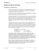
Page 35: ...ring the product by completing and returning a product registration form In the event of a warrantable defect the purchaser shall notify Cobalt with a description of the problem and Cobalt shall provi...

Page 36: ...and professional support representatives for any of the following Name and address of your local dealer Product information and pricing Technical support Upcoming trade show information Phone 217 344...

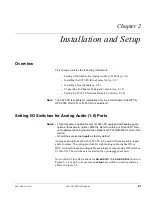
Page 37: ...Ports Notes This procedure is applicable only for 9921 FS equipped with analog audio options for example option ANAIO Refer to catalog or Fusion3G man ual supplement Analog Audio Video Options OPT F3G...

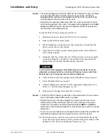
Page 38: ...ear Module s is installed before installing the 9921 FS into the frame slot Damage to card and or Rear Module can occur if module installation is attempted with card already installed in slot Rear of...

Page 39: ...ircuit edge terminals engage fully into the Rear Module mating connector CAUTION If card resists fully engaging in Rear Module mating connector check for alignment and proper insertion in slot tracks...

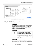
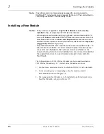
Page 40: ...Rear Module interfaces with expansion piggyback card see Figure 2 3 Note that some Rear Modules and labels have several ventilation holes To allow maximum ventilation it is recommended to place the l...

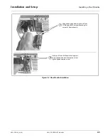
Page 41: ...ing a Rear Module Figure 2 2 Rear Module Installation Align and engage mounting tab on Rear I O Module with the module seating slot on rear of frame chassis Hold top of Rear I O Module flush against f...

Page 42: ...nstalls on slot directly to the left of base Rear Module Note Where a base HV rear module is to be used in conjunction with an expansion rear module a companion HV expansion rear module must also be u...

Page 43: ...connection types described here on Expansion Rear Modules are functional only on cards equipped with corresponding options Base Rear I O Modules provide connections for standard card BNC video and au...

Page 44: ...ly with card option AES installed RM20 9921 D Base Rear Module Provides the following connections Two 3G HD SD SDI video input BNCs SDI IN A and SDI IN B Four AES I O BNC AES 3id input outputs AES I O...

Page 45: ...ng terminals GPO 1 1 and 2 2 Two RS485 serial ports GUI configurable for function COMM1 and COMM2 Four 3G HD SD SDI video output BNCs SDI OUT A thru SDI OUT D Note AES inputs and outputs operational o...

Page 46: ...M20 9921 H Base Rear Module Provides the following connections Two 3G HD SD SDI video input BNCs SDI IN A and SDI IN B Two opto isolated GPI inputs terminals GPI 1 G and GPI 2 G Two SPST NO GPO relay...

Page 47: ...on of each connection is switch configurable Analog Y composite Pr C and Pb coaxial inputs Y IN Pr IN and Pb C IN respectively Analog Y composite Pr C and Pb coaxial outputs Y OUT Pr OUT and Pb C OUT...

Page 48: ...osite output Cmpst OUT RM20 9921 XE Expansion Rear Module Used in conjunction with a base Rear Module to provide the following additional connections Eight analog balanced audio I O AN AUD I O 1 thru...

Page 49: ...ards such as the 9921 FS and especially when equipped with options requiring a piggyback card such as option ANAIO Where a base HV rear module is to be used in conjunction with an expansion rear modul...

Page 50: ...ely RM20 9921 F HV2 Base High Ventilation Rear Module Provides the following connections Two 3G HD SD SDI video inputs SDI IN A and SDI IN B Four AES I O BNC AES 3id input outputs AES I O 1 thru AES I...

Page 51: ...d Pb C OUT respectively Note Analog inputs and outputs operational only with appropriate card option ANA and ANV installed Available equipped with High Density BNC HDBNC or DIN1 0 2 3 connectors as RM...

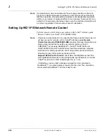
Page 52: ...ote If network remote control is to be used for the frame and the frame has not yet been set up for remote control Cobalt reference guide Remote Control User Guide PN 9000RCS RM provides thorough info...

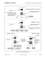
Page 53: ...CB connector G A B G RS 485 Removable Phoenix plug view oriented with top screw terminals up Note RS 485 communication will not work if any of the connections are reversed from that shown here Rear mo...

Page 54: ...2 18 9921 FS PRODUCT MANUAL 9921 FS OM V1 18 This page intentionally blank...

Page 55: ...cessing applications This section describes the user interface controls indicators and displays both on card and remote controls for using the 9921 FS card The 9921 FS functions can be accessed and co...

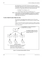
Page 56: ...arameter Menu Overview The functions and related parameters available on the 9921 FS card are organized into function menus which consist of parameter groups as shown below Figure 3 1 shows how the 99...

Page 57: ...Edge Manual Controls This function is currently reserved Input Format Indicators Three blue LEDs indicate the input signal format being received and locked onto by the 9921 FS 3G HD SD Continuous cycl...

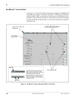
Page 58: ...Items in a list can then be selected using GUI drop down lists Figure 3 3 DashBoard Setup of Example Video Proc Function Select top level menu item Video Proc Set Video Proc enable to On Set Luma Gain...

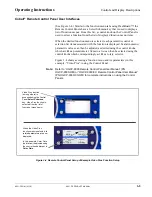
Page 59: ...tiometer Items in a list can then be selected using the control knobs which correspondingly act like a rotary selector Figure 3 4 shows accessing a function menu and its parameters in this example Vid...

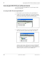
Page 60: ...ew Tree locate the Network Controller Card associated with the frame containing the 9921 FS card to be accessed in this example MFC 8320 N SN 00108053 3 As shown below expand the tree to access the ca...

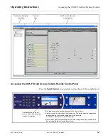
Page 61: ...enu and Controls Pane 9921 FS_DB_ACCESS PNG This display shows the list order number of the device that is ready for selection This display shows the devices assigned to the Control Panel Rotate any k...

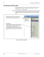
Page 62: ...o Troubleshooting p 3 63 for corrective action Figure 3 5 9921 FS Card Info Utility The Tree View shows the cards seen by DashBoard In this example Network Controller Card MFC 8320 N serial number 805...

Page 63: ...14 16 Note 2 Closed Captioning 21 locked 10 Note 2 Notes 1 The card does not check for conflicts on a given line number Make certain the selected line is available and carrying no other data 2 While r...

Page 64: ...mbers where each function menu item can be found Some functions use sub tabs to help maintain clarity and organization In these instances Table 3 2 shows the ordinate tab along with its sub tabs Highl...

Page 65: ...d with this manual Provides the following Video Proc and Color Correction parametric controls Video Proc Video Proc On Off provides master on off control of all Video Proc functions When set to Off Vi...

Page 66: ...he aggressiveness of sharpening applied to MPEG video Optimum setting results in overall perception of increased sharpness while avoiding pattern noise artifacts Range is 0 thru 255 Sharpness Threshol...

Page 67: ...m is clicked a Confirm pop up appears requesting confirmation Click Yes to proceed with the unity reset Click No to reject unity reset Luma Gain R G B controls Black Gain R G B controls Gamma Factor R...

Page 68: ...0 null 6 8 White Hard Clip Applies white hard clip limiting at specified percentage 50 0 to 109 1 null 109 1 White Soft Clip Applies white soft clip limiting at specified percentage 50 0 to 109 1 null...

Page 69: ...e 13 default SMPTE 12M 2 Noting that the incoming video contains VITC waveform timecode data as shown in the status display set the Source Priority drop down lists to include VITC Waveform timecode da...

Page 70: ...Source Priority 2 selects the second most preferred format and so on See example below Note Disable Output setting should be used with care If Disable Output is selected with alternate intended format...

Page 71: ...t indicates frame count as follows 0 0 Frame 0 0 1 Frame 1 1 0 Frame 2 1 1 Frame 3 29 1 Frame 59 Offset Controls Allows the current timecode count to be advanced or delayed on the output video Offset...

Page 72: ...disables ATC_VITC timecode insertion into the output video and selects the line number for ATC_VITC1 and ATC_VITC2 Note If only one output line is to be used set both controls for the same line number...

Page 73: ...allows line number control null packet insertion if desired and CGMS functions Control set to Enabled always removes incoming CDP and replaces it with the processed CDP Incoming Packet Removal set to...

Page 74: ...th option CGMS CGMS Settings Option CGMS Displays the current status of CGMS insertion CGMS insertion disabled indicates CGMS has been manually disabled using control shown below Error CGMS insertion...

Page 75: ...voked from the choices shown to the left in the time preceding stable lock to external reference Set this control to that of the intended external reference to help ensure smoothest frame sync locking...

Page 76: ...ffset advance is accomplished by hold off of the reference directed release of the frame thereby effectively advancing the program video relative to the reference Minimum Latency Frames Control Minimu...

Page 77: ...status as follows Framesync status running from indicated frame reference Improper or missing framesync reference Framesync derived using card local clock Latency frames selection exceeds limits Note...

Page 78: ...Function Menu List continued NTSC Coded 4 3 1080i Video Signal Up Conversion to 16 9 1080i Video Signal with 16 9 uncorrected signal Without AFD NTSC Coded image on 16 9 display shows letterbox croppi...

Page 79: ...ch received 625i50 SDI video is being up converted to 720p50 The settings shown in the example below provide for directing the scaler to re aspect the 4 3 input video to full centered 16 9 re aspectin...

Page 80: ...ed in this tab overriding any other scaler manual ARC control settings Disabled allows ARC coding processing performed in this tab but does not apply ARC settings in scaler Note This control also appe...

Page 81: ...off WSS format on output AFD Enabled inserts AFD coded WSS on output ETSI Enabled inserts ETSI coded WSS on output VI Output Disable turns off WSS format on output AFD Enabled inserts AFD coded VI on...

Page 82: ...L 4x3 16x9 Center 1011 1 4x3 14x9 Center 1011 1 0 1 NTSC 2 PAL 4x3 14x9 Center 1100 3 4 7 Reserved 1100 0 1 NTSC 2 PAL Reserved 1101 6 4x3 Protect 14x9 1101 6 0 1 NTSC 2 PAL 4x3 Protect 14x9 1110 4x3...

Page 83: ...l with an AFD code and do not perform any re aspecting Separate control groups for 4x3 and 16x9 coded input frames allow custom ARC as well as pan tilt for various coded frames By default each row is...

Page 84: ...r video handled by the card Note Choices shown here are examples only Cards licensed with multiple video inputs such as when licensed for wings and key will have more output source choices such as key...

Page 85: ...that are routed directly to card optional Dolby decoder are detected as Dolby and are then routed via a special path that automatically bypasses SRC However AES inputs to other destinations e g AES em...

Page 86: ...xample above shows various Source selections that direct Emb Ch 1 thru Ch 6 and AES Ch 1 and Ch 2 onto the card internal bus unused bus channels can be set to Silence or Mute Each bus channel provides...

Page 87: ...the selected destination bus channel In this example AES Ch 1 is the source for destination Bus Ch 1 Note AES inputs are only available on card equipped with option AES AES audio I O AES port connecto...

Page 88: ...e in Source drop down list routes a downmixer output channel to be the source for the selected destination bus channel In this example Downmix A L L output channel of downmixer A is the source for des...

Page 89: ...responding audio channel Note Maximum advance delay offset is dependent on video format Refer to Technical Specifications p 1 26 for details Bulk Master Audio Video Delay Control Display Offset contro...

Page 90: ...ignal loss and have failed over to selected choices Analog Ch 1 and Analog Ch 2 as shown by the Secondary Failover indication for these primary channels Audio Failover master enable disable control Fa...

Page 91: ...el Selection Separate L R C Ls Rs drop downs for each of the four independent downmixers A thru D that directs any combination of card audio inputs listed below to each downmixer input channel Embed C...

Page 92: ...ault 3 dB Note Default setting is recommended to maintain center channel predominance in downmix representative to that of the original source 5 channel mix Surround Mix Ratio Control Adjusts the atte...

Page 93: ...gain engaged for use Note Default threshold and holdoff settings shown here are recommended for typical use For Failover indicator to properly function and for automatic downmix to route to card proce...

Page 94: ...h 1 Ch 8 Emb Ch 1 Ch 16 Flex Mix B Flex Mix C Flex Mix D To Audio Bus Input Routing Emb Ch 1 Emb Ch 2 Emb Ch 3 Emb Ch 4 Flex Mix 5 Flex Mix 6 Flex Mix 7 Flex Mix 8 Emb Ch 5 Emb Ch 6 Emb Ch 11 Emb Ch 1...

Page 95: ...s any other audio input source Note See the examples on the previous page for providing various types of mixers by applying a common Flex Mix Bus to various input channels Dolby E Alignment Provides s...

Page 96: ...g selections using the Emb Audio Out and AES Audio Out sub tabs that direct upmix outputs L thru Rs to Embedded outputs Ch 1 thru Ch 6 the pre upmix Bus Ch1 and Ch 2 sources to Embedded outputs Ch 7 a...

Page 97: ...ixer Channels as Source for Embedded Channel Output Upmix L thru Upmix Rs range in Source drop down list routes an upmixed channel to be the source for the selected embedded output channel In this exa...

Page 98: ...e as Source for Embedded Channel Output Silence selection in Source drop down list mutes the selected embedded output channel Use this setting for any unused embedded output channels In this example S...

Page 99: ...the card Note Cards with option AES16 do not share AES input and output BNC ports 16 channels of AES input embedding is available using the Audio Bus Input Routing Controls with 16 channels of AES out...

Page 100: ...Dolby L and Encoded Dolby R selection in Source drop down list routes a Dolby encoded pair from any of the card s Dolby encoders A up to D to be the source for the selected AES output channel In this...

Page 101: ...w 5 1 content generated by the upmixer regardless of original signal level or content Bypass Manual disable bypasses the upmixer When bypassed the six input audio channels pass unaffected to the upmix...

Page 102: ...enabled set to Always Upmix and is currently up mixing received stereo pair and overwriting the six selected channels with new 5 1 upmix Bypassed Indicates upmixer is manually disabled set to Bypass a...

Page 103: ...center C channel with any center channel content removed from L and R channels Higher settings progressively blend respective L and R mono content back into L and R channels with 100 setting resulting...

Page 104: ...listed to the left and shown below None selection frees the port to be used as an input VBI SMPTE 2020 Embedding Source Selector For VBI embedding at the card SDI output selects the source of metadata...

Page 105: ...encoding is active it is recommended that any metadata not specifically related to that being used by the encoder be removed or replaced with metadata being used by the encoder and also that the line...

Page 106: ...any of 64 user defined presets to be invoked when the state corresponding to the drop down becomes true Note No Preset setting should be considered and used for any logic state that is not specificall...

Page 107: ...ondition The state shown in bold is the currently active state Binary GPI coding triggers on conditions that consider state combinations on both GPI 1 and GPI 2 for the four state combinations on the...

Page 108: ...r preset as shown in the examples here Up to 62 ASCII characters can be entered Preset Save stores all current card control settings for the selected preset in this example pressing Save for Preset 1...

Page 109: ...based loading settings performed here cannot be saved to presets Event Preset Load Select Controls Event based preset loading checks for up to three conditions as described below to all be true and t...

Page 110: ...nditions are triggered upon start of event Any event based setup must be done in advance of the triggering event in order for event to be detected Loss of true conditions does not disengage an event b...

Page 111: ...If Audio Silence Event as a trigger condition is not desired it can be set to Don t Care on the Event Based Loading sub tab or globally set to Disabled here Failover controls set the conditions that c...

Page 112: ...h the network main audio and SAP audio with that from an EAS receiver on AES pair 2 using a preset invoked by a ground closure on GPI 2 A thru E on sheets 2 through 4 show the setups using the DashBoa...

Page 113: ...ting required to get all channels shown in A D and E into the card processing is accomplished using the Audio Bus Input Routing Controls tab as shown to the right for this example All signals coming i...

Page 114: ...audio now as channels Upmix L thru Upmix Rs is then fed to the 5 1 channel inputs of the Loudness Processing inputs The stereo SAP pair now on channels Bus Ch 7 and Ch 8 is routed to the L and R inpu...

Page 115: ...5 1 audio with no other downstream routing changes required With the unused upmixer input channels set to silence this will force an upmix of the received stereo pair in this example This routing cha...

Page 116: ...tion upon a GPI 1 closure if GPI 2 is open or invoke Preset 3 EAS insertion unconditionally upon a GPI 2 closure as shown to the right Preset 1 applied to GPI 1 Open GPI 2 Open recalls the normal rout...

Page 117: ...te control systems all to varying degrees provide error and failure indications Depending on how the 9921 FS card is being used i e standalone or network controlled through DashBoard or a Remote Contr...

Page 118: ...bbreviated code showing menu and menu selections When in a menu displaying a parameter setting the display shows parametric scalar value and sign where applicable Card Edge Manual Controls This functi...

Page 119: ...cting to the frame or LAN all controls are grayed out as shown in the example here Gray indicator icon in Card Access Navigation Tree pane shows card s are not being seen by DashBoard due to lack of c...

Page 120: ...is example Card Info is displayed for frame Network Controller Card Status for selected card is shown here in this example connection OK and Fan Door Open alert Card general information is displayed i...

Page 121: ...card and network remote controls the respective indicators and displays are individually described in this section Table 3 3 Basic Troubleshooting Checks Item Checks Verify for power presence On both...

Page 122: ...changed from expected settings Event based preset inadvertently invoked Event based preset loading should be set to Disabled if this function is not to be used Read and understand this control descrip...

Page 123: ...Controls tab GPI Coding set to Binary with no controlled GPI source connected to GPI inputs If GPI is not to be used make certain GPI Coding control on GPI Controls tab is set to Disabled If control...

Page 124: ...order listed as necessary until normal operation is restored 2 Hold the lower button in and slide the card into a powered slot 3 With card fully in slot continue holding the button for about 3 second...

Page 125: ...ll as specific shipping instructions If required a temporary replacement item will be made available at a nominal charge Any shipping costs incurred are the customer s responsibility All products ship...

Page 126: ...3 72 9921 FS PRODUCT MANUAL 9921 FS OM V1 18 This page intentionally blank...

Page 127: ......

Page 128: ...Cobalt Digital Inc 2506 Galen Drive Champaign IL 61821 Voice 217 344 1243 Fax 217 344 1245 www cobaltdigital com 9921 FS OM V1 18 Printed in USA...

Reviews: