9921-FS-OM (V1.18)
9921-FS PRODUCT MANUAL
3-33
Operating Instructions
9921-FS Function Menu List and Descriptions
(continued)
Note: •
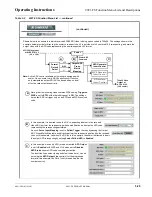
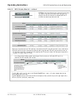
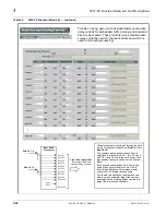
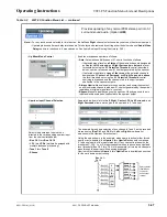
Default factory preset routing routes embedded Ch 1 thru Ch 16 to bus channels Bus Ch 1 thru Bus Ch 16.
•
Bus Ch 2 thru Bus Ch 16 have controls identical to the controls described here for Bus Ch 1. Therefore, only the
Bus Ch 1 controls are shown here.
•
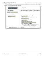
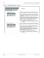
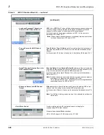
For each bus channel, its source should be considered and appropriately set. Unused bus channels should be set to the
Silence selection.
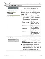
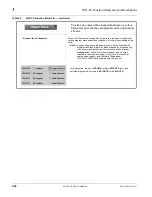
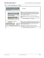
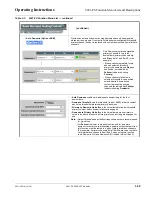
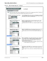
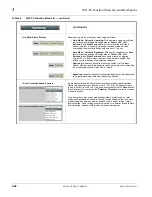
• Bus Channel Source
Using the Source drop-down list, selects the audio input source to be
directed to the corresponding bus channel from the choices described
below.
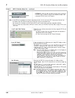
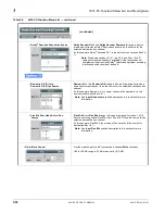
• Embedded Ch 1 thru Ch 16 as Source
Embed Ch 1 thru Embed Ch 16 range in Source drop-down list routes an
embedded channel (Ch 1 thru Ch 16) to be the source for the selected
destination bus channel.
(In this example, Embed Ch 1 (embedded Ch 1) is the source for destination
Bus Ch 1)
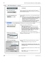
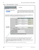
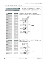
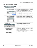
• AES Ch 1 thru AES Ch 16 as Source
AES Ch 1 thru AES Ch 16 range in Source drop-down list routes an AES
channel (Ch 1 thru Ch 16) to be the source for the selected destination bus
channel.
(In this example, AES Ch 1 is the source for destination Bus Ch 1)
Note: • AES inputs are only available on card equipped with AES
(AES audio I/O).
• AES port connectors (channel pairs) on the card rear module are
set as either Input or Output using the AES Port Direction control
on the Output Audio Routing/Controls DashBoard tab. Make certain
an AES channel pair is not being used an output before assigning it
as a source here. (Refer to Output Audio Routing/Controls (p. 3-42)
for more information.)
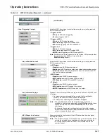
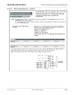
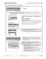
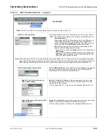
• Analog Ch 1 thru Ch 8 as Source
Analog Ch 1 thru Analog Ch 8 range in Source drop-down list routes an
analog channel (Ch 1 thru Ch 8) to be the source for the selected destination
bus channel.
(In this example, Analog Ch 1 is the source for destination Bus Ch 1)
Note: • Analog audio inputs are only available on card equipped with
ANAIO, +ANAVI, or +ANAVO (analog audio I/O).
• Analog audio connectors on the card rear module are set as either
Input or Output using the AN-AUD I/O (1-8) Mode Switches,
located on the 9921-FS analog audio piggyback PCB. Make certain
an analog channel is not being used an output before assigning it
as a source here. (Refer to Setting I/O Switches for Analog Audio
(1-8) Ports (p. 2-1) for more information.)
Table 3-2
9921-FS Function Menu List — continued
•
•
•
•
•
•
•
•
•

