background image

To install the EXPLORER 7100GX

3-2

Chapter 3:  Installation & start up

98-147366-A

3.1.2

Initial inspection

Inspect the cases immediately upon receipt for evidence of damage during transport. If the 
shipping material is severely damaged or water stained, request that the carrier's agent be 
present when opening the cases. Save all packing material for future use.

After unpacking the system, inspect it thoroughly for hidden damage and loose 
components or fittings. If the contents are incomplete, if there is mechanical damage or 
defect, or if the system does not work properly, notify your dealer.

3.2

To install the EXPLORER 7100GX

3.2.1

Prerequisites

Wind speed considerations

The antenna is designed to operate under wind speeds of 48 km/h (30 mph) gusting up to 
72 km/h (45 mph) while anchored and survive winds of 100 km/h (62 mph) gusting up to 
128 km/h (80 mph) while anchored. Note that the antenna may point away from the 
satellite in winds blowing faster than the operational wind speed limit. 

WARNING!

To avoid electric shock, do not apply power to the system 

if there is any sign of shipping damage to any part of the front or rear 
panel or the outer cover. Read the safety summary at the front of this 
manual before installing or operating the system.

Note

If the look angle is less than 12 degrees it is important to level the terminal.

Important

Do not operate the terminal at wind speeds exceeding the operational wind 
speeds. In case the wind speeds exceed the operational wind speed limit 
while the antenna is already assembled or operational, bring the antenna to 
the stow position. In case the wind speeds exceed the survival wind speed 
limit while the antenna is operational, bring the antenna manually back to the 
stow position.

Summary of Contents for EXPLORER 7100GX

Page 1: ...EXPLORER 7100GX Installation and user manual 1 0 m Drive Away VSAT System for Inmarsat GX ...

Page 2: ......

Page 3: ...EXPLORER 7100GX 1 0 m Drive Away VSAT System for Inmarsat GX Installation and user manual Document number 98 147366 A Release date 2 September 2015 ...

Page 4: ...the governing text Thrane Thrane A S is trading as Cobham SATCOM Copyright 2015 Thrane Thrane A S All rights reserved Trademark acknowledgements Inmarsat is a registered trademark of the International Maritime Satellite Organisation IMSO and is licensed by IMSO to Inmarsat Limited and Inmarsat Ventures plc Other product and company names mentioned in this manual may be trademarks or trade names of...

Page 5: ...ly The voltage range for the EXPLORER 7100GX is 100 240 VAC nominal 4 A 50 60 Hz Do not operate in an explosive atmosphere Do not operate the equipment in the presence of flammable gases or fumes Operation of any electrical equipment in such an environment constitutes a definite safety hazard To drive with the antenna installed The antenna must be stowed when you drive the vehicle The maximum spee...

Page 6: ... harmful interference to radio communications However there is no guarantee that interference will not occur in a particular installation If this equipment does cause harmful interference to radio or television reception which can be determined by turning the equipment off and on the user is encouraged to try to correct the interference by one or more of the following measures Reorient or relocate...

Page 7: ...3 Part numbers 2 8 Chapter 3 Installation start up 3 1 What s in the box 3 1 3 1 1 To unpack 3 1 3 1 2 Initial inspection 3 2 3 2 To install the EXPLORER 7100GX 3 2 3 2 1 Prerequisites 3 2 3 2 2 Vehicle installation 3 3 3 2 3 Installation of the ACU and GMU 3 3 3 2 4 To connect the ACU GMU and antenna pedestal 3 3 3 3 Start up and daily use 3 5 3 3 1 To deploy the antenna 3 5 3 3 2 To jog the ante...

Page 8: ...date 5 7 5 1 7 Proxy server settings in your browser 5 8 5 2 Software update 5 9 5 2 1 Prerequisites 5 9 5 2 2 Software update procedure 5 9 5 3 Status signalling with LEDs and status messages 5 12 5 3 1 LEDs on the keypad of the EXPLORER 7100GX 5 12 5 3 2 Status information of the modem 5 13 5 4 To return units for repair 5 14 Appendix A Technical specifications A 1 Specifications A 1 A 2 Product...

Page 9: ...observe all safety requirements listed in the beginning of this manual and install the system according to the guidelines in this manual 1 1 2 Software version This manual is intended for EXPLORER 7100GX with software version 1 50 Antenna and ACU The GX modem Core module software version is shown in its own web interface 1 1 3 Typography In this manual typography is used as indicated below Bold is...

Page 10: ... gives information that is important to the user e g to make the system work properly This text does not concern damage on equipment or personal safety All personnel who operate equipment or do maintenance as specified in this manual must know and follow the safety precautions The warnings and cautions that follow apply to all parts of this manual WARNING Before using any material refer to the man...

Page 11: ...igh reliability It is driven by a low backlash gearbox with DC motors and all drive components are high strength steel encased in lubricated for life housings For further details see the technical specifications All of the EXPLORER series terminals are easy to install setup and commission by a non specialist technician The system has the following major components 1 2 axis motorized antenna positi...

Page 12: ...X modem 2 1 2 Global Express service The EXPLORER 7100GX is a unique GX antenna system operating in the K Ka band 19 2 to 30 GHz It is used with the Global Xpress service from Inmarsat delivering consistent high performance download speeds of up to 50 Mbps and 5 Mbps over the uplink The following figure shows the coverage map of the GX service at global service introduction 2 1 3 Service activatio...

Page 13: ...n a redundant configuration to achieve a lightweight very stiff drive system with zero backlash This high tech performance is achieved using low tech components by simply wrapping the cable around the drive capstan several times before wrapping the larger drive drum This method results in a minimum free length of cable The load cable on the main drum is exponentially reduced as it is wrapped aroun...

Page 14: ...stem Gear sets are encased in a sealed housing that allows them to be continuously lubricated in synthetic oil which maximizes gear efficiency and minimizes wear Motor drives Lightweight reliable DC motors with integrated gearboxes are used for the azimuth and elevation These motors provide the best torque to weight ratio as well as allowing dual speed operation for slewing and peaking These motor...

Page 15: ...des 2 2 3 Antenna Control Unit ACU and GX Modem Unit GMU The system s ACU and GMU are packaged into two 1RU 19 inch rack mount indoor units that are rated IP30 The ACU and GMU have an On Off power switch at the front ACU The ACU serves as the interface between the GMU and the antenna The ACU provides power to the antenna The ACU has the following connectors Figure 2 5 Components of the RF assembly...

Page 16: ...iption of the LED light indicators see LEDs on the keypad of the EXPLORER 7100GX on page 5 12 2 2 5 Web interface for setup and troubleshooting To fully configure the EXPLORER 7100GX use the built in web interface Installation of software is not necessary you can use a standard Internet browser The web interface is mainly used for first time setup of the LAN ports WLAN use and administrating admin...

Page 17: ...onnectors LAN 2 to LAN 4 are user ports for Internet etc configured by the GX modem LAN 5 is used to control the GMU The EXPLORER 7100GX has a WLAN module Access to one of the LAN ports using WLAN must be set up in the web interface see To configure the LAN network on page 4 5 2 2 7 Power Supply The internal power input for the ACU and GMU is specified as 100 240 VAC for more details see Specifica...

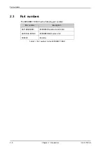
Page 18: ...147366 A 2 3 Part numbers The EXPLORER 7100GX has the following part numbers Part number Description 407140B 50001 EXPLORER Antenna Control Unit 407023 B 00500 EXPLORER GX Modem Unit 300224 Antenna Table 2 1 Part numbers for the EXPLORER 7100GX ...

Page 19: ...enna ACU and GMU and check that the following items are present Antenna EXPLORER 7140B ACU Stow indication connector Accessory kit for EXPLORER 7140B ACU RJ45 patch cable 1 pce Ethernet cable 2 m 1 pce Power cable WLAN Antenna User IO cable for future use Hand crank EXPLORER 7023B GMU Accessory kit for EXPLORER 7023B GMU Wiecon 3 5 mm spacing 4 pol connector for cable RJ45 patch cable 1 pce Power ...

Page 20: ...h 45 mph while anchored and survive winds of 100 km h 62 mph gusting up to 128 km h 80 mph while anchored Note that the antenna may point away from the satellite in winds blowing faster than the operational wind speed limit WARNING To avoid electric shock do not apply power to the system if there is any sign of shipping damage to any part of the front or rear panel or the outer cover Read the safe...

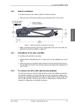
Page 21: ...referably next to each other 2 Mount the screws on each side through the holes in the front and fasten the screws to the rack Make sure that the unit is mounted securely according to the requirements for your 19 rack 3 2 4 To connect the ACU GMU and antenna pedestal A total of two AC power connections must be made a total of five cables will connect the ACU and GMU together Four cables will extend...

Page 22: ...o the ACU s BUC Tx port 8 Connect the Control port on the pedestal bulkhead to the ACU s ODU Power Comm port 9 Connect the BUC Power comm on the pedestal bulkhead to the ACU s BUC Power comm port 10 Connect the GMU to an AC power source 11 Connect the ACU to an AC power source 12 Use LAN1 on the ACU to access the web interface of the ACU 13 Use LAN2 LAN3 and LAN4 on the ACU to connect user PCs Int...

Page 23: ...or a PC and the built in web interface To learn how to use the keypad see Navigating the menus on page 4 15 3 3 1 To deploy the antenna To deploy the antenna using the keypad and display 1 Switch on the ACU and the GMU 2 After power up wait until the ACU display shows READY TO MOVE 3 Press OK on the ACU display to deploy the antenna or after a manual stop of the antenna 1 Press OK to scroll to the...

Page 24: ...e login screen is displayed you have verified that the connection can be established 5 Type in the user name admin and the password 1234 to access the Dashboard as an administrator 6 Wait until the status shows READY TO MOVE 7 Navigate to the page SERVICE ANTENNA and click the button Deploy 8 Wait until the status shows Deployed 3 3 2 To jog the antenna When the antenna is deployed you can jog the...

Page 25: ...ick Stop 3 3 3 To stow the antenna Set the antenna into the stow position before moving the vehicle To stow the antenna using the keypad and display To learn how to use the keypad see Navigating the menus on page 4 15 1 Press OK to scroll to the COMMAND page and press OK again to access the page 2 Press until STOW is selected and press OK 3 Wait until the status shows STOWED To stow the antenna us...

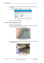
Page 26: ...Stowed To stow the antenna using the hand crank 1 Make sure the power is switched off 2 Ensure that the elevation angle allows for free movement in azimuth If needed use the manual drive handle to increase the elevation angle 3 Manually drive the azimuth angle to approx 0 degrees so that the antenna boom points in the direction of the base Figure 3 7 To stow the antenna using the web interface Fig...

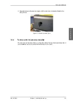
Page 27: ...rease the elevation angle until the antenna is completely folded to the stow position 3 3 4 To drive with the antenna installed The antenna must be stowed when you drive the vehicle The maximum speed depends on your installation but it must never exceed 100 mph or 161 km h Figure 3 10 Elevation manual drive ...

Page 28: ...Start up and daily use 3 10 Chapter 3 Installation start up 98 147366 A ...

Page 29: ...wer LED Green Logon LED Off Fail Pass LED Flashing green during power on self test after that steady green 2 Connect a PC to the LAN1 connector Service port standard leftmost Use shielded LAN cables You can configure the network according to your requirements See To configure the LAN network on page 4 5 for more information 3 Open your Internet browser and enter the IP address of the EXPLORER 7100...

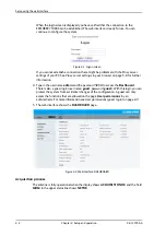
Page 30: ...on 4 Type in the user name admin and the password 1234 to access the Dashboard There is also a guest login user name guest password guest With this login you can protect the system from accidental changes of the configuration A guest can only access the functions that are allowed on the page User permissions by an administrator For more information see User permissions guest login on page 4 11 5 T...

Page 31: ...the site map to go directly to the page or display the respective submenu The DASHBOARD is the first screen that is displayed when the user or administrator enters the IP address of the web interface of the ACU It shows the properties and status of the EXPLORER 7100GX The web interface has the following sections Figure 4 3 Topics in the web interface SITE MAP Figure 4 4 Web interface DASHBOARD 1 2...

Page 32: ...status and settings click the relevant subject in the navigation pane or click the relevant icon in the icon bar The status or settings are displayed in the contents section To get an overview over the submenus available click SITE MAP in the navigation pane Click on items in the site map to go directly to the relevant location Information fields on the Dashboard Icon Explanation An event is activ...

Page 33: ...lue for azimuth Elevation Current value for elevation RX RF frequency Ka band receiving frequency auto selected by modem Tuner signal strength Current tuner signal strength Tuner mode GSC GX or Narrow band Tracking RF frequency Current RF tracking frequency Antenna TX allowed Not allowed or Allowed Modem RX status Not locked or Locked ACU part name Antenna part name ACU serial number Antenna seria...

Page 34: ...change the name Letters a z digits 0 9 and hyphen are allowed as legal characters Note The host name must start with a letter LAN Port 1 LAN port 1 is dedicated as the service port By default this port has the static IP address http 192 168 0 1 the current value can be displayed in the EXPLORER 7100GX display The service port has 3 modes Static default DHCP client Used when the antenna is on a loc...

Page 35: ...t membership table The VLAN port membership table Virtual LAN is configured by the modem The table is useful when troubleshooting LAN Port 2 3 and 4 User data ports configured automatically by the modem The Virtual LAN VLAN table shows this configuration LAN Port 5 No connector only internal connection This network is connected to the modem iDirect GX Modem It is set to static IP WLAN The wireless...

Page 36: ...d WLAN access point is hidden 6 Type in the SSID of your choice or accept the default SSID which is Cobham The SSID is the name of the wireless local area network It is a text with maximum 32 characters 7 Select the Security standard Select one of the following encryption standards Disabled default WEP 64 enter the encryption key in hexadecimal format WEP 128 enter the encryption key in hexadecima...

Page 37: ...d User permissions guest login Import and export of a system configuration Reset to factory default Access to the administration settings user name password You can logon as an administrator or as guest user name guest password guest The Administration settings require an Administration user name and password To log on as administrator do as follows 1 Open your Internet browser and enter the IP ad...

Page 38: ...2 Type in the new password and retype it on the next line 3 Click Change At the next logon the new password is required To reset the administrator password do as follows 1 Contact your service partner for a reset code Report the serial number of the ACU You find it in the Dashboard ACU serial number 2 Click the link Forgot administrator password on the LOGON page see Figure 4 7 Web interface Logon...

Page 39: ...he pages are read only changes cannot be made by the guest user Change network Locks the page SETTINGS Network Use this page to change IP configuration of the LAN connectors of the ACU For further information see To configure the LAN network on page 4 5 Modify LNB data Locks the page SERVICE LNB for guest users This page is used when exchanging an LNB Control Modem Locks the page SERVICE Modem for...

Page 40: ...ile and locate and double click the configuration file cfg file 3 In the web interface click the button Upload To clone a system configuration do as follows 1 Reset to factory default see the following section for details 2 Import a configuration from file see section above 4 1 9 Reset to factory default When resetting EXPLORER 7100GX to factory default the following settings are deleted or reset ...

Page 41: ...ct the reset level Level 0 Soft Reset Power cycle of the GX modem Do not use Level 2 Diagnostic Test Mode Only connection to the GX modem is the serial RS 232 interface all other connections are shut down Do not use Level 3 Default Factory Configuration Figure 4 11 Web interface ADMINISTRATION Factory default CAUTION Administrators only Close this page for guest users see User permissions guest lo...

Page 42: ...ired SAFE MODE error followed by an error description 2 Current menu see The menu tree on page 4 15 3 NAV Navigational information First letter G Valid position signal received from the GNSPS module or g No valid GNSS fix Second letter H Valid heading data or h No valid heading data 4 MDM Current status of the modem TEST ERROR READY INIT RXOK ACQ NETOK RESET OFF 5 LAN LAN connectors used 1 2 3 4 6...

Page 43: ...Press OK to select a setting Press again to move one level up If applicable confirm to store the new setting by pressing OK 4 2 3 The menu tree In the menu tree you can see how the system has been configured To enter satellite information use a connected PC and the web interface Figure 4 14 Menu tree in the display 17 11 32 17 1 36 203 66 9 56 216 32 17 1 17 11 67 7 9 7 21 087 36 7 78 21 78 7 3 6 ...

Page 44: ...TE Current satellite information This information is selected using the web interface NETWORK Shows the IP addresses and netmasks of the LAN connectors of the ACU and the management mask EVENTS View system events Active events are shown as X ACTIVE EVENTS in the MAIN display Press OK to update the list Table 4 5 Top level menus 0DLQ 1 9 0 0 1 72 1 48 6 7 21 2 6 7 5 7 0 5 MANUAL POINTING Descriptio...

Page 45: ...em SIGNAL LEVEL Current input signal level from the GX modem in dB NET LED Modem status Steady or flashing green yellow red OFF STAT LED TX LED RX1 LED RX2 LED PWR LED TEMP LED FAN LED Table 4 8 MODEM menu SATELLITE Description POSITION Current satellite position RX FREQ Current RX frequency LNB LO LNB LO frequency BUC LO BUC LO frequency Table 4 9 SATELLITE menu NETWORK Description PORT1 IP Curre...

Page 46: ... is the current brightness value 2 Hold OK press to brighten or to darken display 3 Release OK to leave the brightness menu EVENT Description EVENT In this menu all active events are listed Use and to go through the active events Events can be of the type WARNING or ERROR If a new event occurs or there is a change in the event list while you are in the EVENTS menu a is shown in the upper left corn...

Page 47: ...lem contact your service provider 5 1 1 Preventative maintenance The EXPLORER 7100GX is constructed to require a minimum amount of regular maintenance Make the following checks on a regular basis Inspect the reflector front surface for physical damage including chips and cracks Any substantial damage can affect antenna performance and may require the reflector to be replaced Check the feed horn fo...

Page 48: ...lick the button Download The report txt file is downloaded to your computer The diagnostics report contains information relevant for the service personnel It is also useful documentation of the current setup The report contains all parameters set during configuration The main sections are Software System Hardware Setup System data Network LAN and WLAN configuration Modems Satellites Satellites pro...

Page 49: ...ode ID explanation and remedy see System messages on page B 1 Self test You can start a self test of the EXPLORER 7100GX antenna and ACU 1 Click Self test in the HELPDESK page 2 Click the menu item Self test 5 1 3 Reset To reset the antenna do the following 1 Press and hold and until the ACU display shuts down and the antenna reboots 2 Wait until the antenna has rebooted and is operational again T...

Page 50: ...rofile The page automatically displays the parameters available for the selected VSAT modem profile For instructions how to add a VSAT modem profile see VSAT modem profile New entry and Edit on page 5 5 4 Enter the data for the satellite if any For satellite data see www lyngsat com 5 Click Apply to save the settings for the satellite profile VSAT modem profiles On the page VSAT modem profiles you...

Page 51: ...sted in the drop down list VSAT modem 2 Fill in a VSAT modem profile name of your own choice 3 Select the Generic GX modem for troubleshooting from the drop down list 4 Click Apply to add the new profile to the list of VSAT modem profiles or to accept the edits For a generic modem you enter all parameters in the satellite profile Figure 5 5 Web interface SETTINGS VSAT modem profile supported modem...

Page 52: ...ommissioning 6 Click Start Once commissioning is completed the antenna will search for the I5 satellite with the highest elevation 7 The antenna will find the satellite and the GMU will perform necessary steps to enter the network software upgrades if available WARNING For your safety Active RF transmission may occur during an OTC procedure Software updates may also occur yet the system is in rece...

Page 53: ... the new LNB do as follows 1 Select SERVICE LNB 2 Enter the new values LNB LPN LNB model number LNB LSN LNB serial number in Inmarsat format L MID Manufacturer ID LNB FID LNB function ID typically empty shown with a 3 Click Apply to save the new settings 4 Restart the system and wait for Net ok in the display 5 If you have replaced the RF assembly you must make a One Touch Commissioning see GX Mod...

Page 54: ...for the web interface only if you wish Consult your browser help for information To disable the use of a Proxy server completely do as follows 1 In Microsoft Internet Explorer select Tools Internet Options Connections LAN Settings 2 Clear the box labeled Use a proxy server for your LAN 3 Click OK When the proxy server settings are disabled close and restart your browser You may need to change this...

Page 55: ... on the ACU 2 Connect a PC to LAN interface 1 Service port standard If you want to use another LAN port to access the web interface you must configure it according to your network requirements See To configure the LAN network on page 4 5 for more information 3 Open your Internet browser and enter the IP address of the EXPLORER 7100GX The default IP address is http 192 168 0 1 4 Type in the user na...

Page 56: ...a failed software upload turn off the ACU and turn it on again Then repeat the upload procedure as described in Software update on page 5 9 To verify the software update 1 The software version can be viewed in the DASHBOARD window of the web interface 2 After completing the software update procedure the EXPLORER 7100GX will perform a POST Power On Self Test 3 When the POST has finished the green P...

Page 57: ...covery safe mode If the EXPLORER 7100GX has become inoperative a software recovery update may bring it back into an operational state To make a software recovery do as follows 1 During reboot push and hold the arrow keys and on the keypad The text safe mode is shown in the display The network settings are reset to factory default http 192 168 0 1 2 Open an Internet browser and enter the address ht...

Page 58: ...ethods for signalling the system status There are LEDs on the front panel of the ACU to signal Power on off Logon and Fail Pass There is also the built in web interface of the ACU which shows any events BITE error codes with a short message describing each error This is also displayed in the ACU In an error situation one of the following system status messages may be shown ACU POST error ADU POST ...

Page 59: ...hing green red or yellow NET LED STAT LED TX LED RX1 LED RX2 LED PWR LED TEMP LED FAN LED Fail Pass LED Steady red A fault which prevents operation is present in the system ACU ODU MODEM Flashing green A Power On Self Test POST or Person Activated Self Test PAST in progress The current status is displayed Flashing red Active BITE failure or warning The event is shown in the ACU display Steady gree...

Page 60: ...r details on www cobham com communications and connectivity satcom where you also find the Cobham SATCOM Self Service Center web portal which may help you solve the problem Your dealer installer or Cobham SATCOM partner will assist you whether the need is user training technical support arranging on site repair or sending the product for repair Your dealer installer or Cobham SATCOM partner will a...

Page 61: ...zation LHCP RHCP Max On Axis EIRP Spectral Density dBW 40kHz per FCC 25 138 36 5 G T dB K 30EL with 1 5dB NF LNB 20C Midband 19 9 BUC output power P1dB W 5 Reflector Size 1 0 m Optics Offset Prime focus 0 8 F D Construction Single piece resin fibre composite Mechanical characteristics Axis Drive System 2 Axis positioner Mount Geometry Elevation over azimuth Travel Azimuth 200 from stow position Tr...

Page 62: ... 5 kg 10 lbs ACU approx dimensions 1 U 19 inch 4 4 x 48 x 33 cm 1 75 x 19 x 13 inch Environmental characteristics Wind Speed Operational 72 km h 45 mph Survival deployed 105 km h 55 mph Survival stowed 129 km h 80 mph Temperature Operational antenna 30 to 52 C 22 to 125 F Temperature Storage antenna 40 to 60 C 40 to 140 F Temperature Operational ACU and GMU 25 to 55 C 13 to 131 F Temperature Stora...

Page 63: ...nical specifications A 3 Technical specifications A 2 Product Dimensions The dimensions shown here are in centimetres with inches shown in brackets A 2 1 Side view stowed A 2 2 Top view stowed Figure A 1 Side view stowed Figure A 2 Top view stowed ...

Page 64: ...Product Dimensions A 4 Appendix A Technical specifications 98 147366 A A 2 3 Side view deployed Figure A 3 Side view deployed ...

Page 65: ...Product Dimensions 98 147366 A Appendix A Technical specifications A 5 Technical specifications A 2 4 Measures for antenna installation Figure A 4 Measures for antenna installation ...

Page 66: ...Product Dimensions A 6 Appendix A Technical specifications 98 147366 A ...

Page 67: ...quires your action it issues an event message and the red Fail Pass LED in the LED panel of the ACU is lit As long as an event is active it is shown in the ACU display and in the web interface in HELPDESK Event list or click the event icon on the DASHBOARD State the Event ID when contacting your service partner The event description might contain a number of digits in brackets e g 00000005 This is...

Page 68: ...reference signal is not present Whether this error Rx or Tx reference depends on the users selection on the modem profile page Make sure VMU Rx Tx cable is connected and that the VMU is configured to output the RX TX reference signal 08078 0 ADM WARNING VMU TX frequency invalid VSAT modem unit provided a TX frequency of zero This may degrade tx performance To remove this warning re configure the m...

Page 69: ...ge is out of range The LNB might be switched off to protect the power supply circuitry Reactivate satellite profile to try again check LNB cable and surroundings if the problem persists 08880 0 ADM ERROR WLAN configuration error Configuration of WLAN module failed 08A00 0 ADM WARNING GX Core Module fan There is a problem with the Core Module fan Check clean and replace if necessary 08A01 0 ADM WAR...

Page 70: ...nation 0C001 Error Compass dish Not seeing the compass 0C002 Error GNSS position velocity Not detecting any GPS satellite 0C003 Error Base angle level Antenna base angle exceeds 8 Level the antenna 0C005 Error AZ major over travel Antenna has been driven beyond the azimuth electrical limit 0C006 Warning AZ over travel Antenna has reached the electrical limit 0C007 Error SNR communication SSI value...

Page 71: ...98 147366 A C 1 Appendix C Approvals Approvals C This appendix lists the approvals for EXPLORER 7100GX ...

Page 72: ...C 2 Appendix C Approvals 98 147366 A ...
Page 73: ...m e g GPS GPS Global Positioning System A system of satellites computers and receivers that is able to determine the latitude and longitude of a receiver on Earth by calculating the time difference for signals from different satellites to reach the receiver GSC Global Signaling Channel GX Global Xpress high speed broadband network a worldwide Ka band mobile satellite system I IFL Inter Facility Li...

Page 74: ...ment demodulator for processing P PAST Person Activated Self Test POST Power On Self Test A system test that is activated each time the system is powered on R RF Radio Frequency Electromagnetic wave frequencies between about 3 kHz and about 300 GHz including the frequencies used for communications signals radio television cell phone and satellite transmissions or radar signals RU Rack Unit S SSID ...

Page 75: ...ator password 4 10 change network setting 4 11 clone system 4 12 clonesystem 4 12 compass automatic 4 9 manual 4 9 configuration copy 4 11 export 4 11 import 4 11 LAN network 4 5 site map 4 3 step by step 4 1 Configuration program 4 1 connect web interface 4 1 contact information 5 1 Country selecting for WLAN 4 8 D default reset to factory settings 4 12 DHCP client 4 7 DHCP server 4 7 diagnostic ...

Page 76: ...eb interface 4 11 LNB exchange 5 7 LO frequencies 4 14 load configuration 4 11 log off administrator 4 11 login guest 4 11 web interface 4 2 logon administrator web interface 4 9 M manual pointing 4 16 messages B 1 microwave radiation iii modem direct access with commands 4 6 reset 4 11 web interface 5 6 N navigation 4 4 navigation in web interface 4 4 network LAN setup 4 5 notifications 5 3 O One...

Page 77: ...A 1 speed limit iii SSID 4 8 static IP 4 1 static IP address 4 7 status messages 5 12 stow antenna 3 7 support contact information 5 1 system ACU reset keys to press 5 3 clone 4 12 system configuration copy 4 11 System messages B 1 T technical data A 1 troubleshooting diagnostic report 5 2 U updating software 5 9 upload configuration 4 11 user permissions setup 4 11 V vehicle speed iii VLAN port m...

Page 78: ...98 147366 A www cobham com satcom ...

Reviews: