background image


Instruction Manual - Original Version 


Page 33 of 50 


3.


Upload and Print. 

Choose G-code file to be uploaded to printer. Print starts immediately after 

upload.


4.


Status bar

 indicating state of machine 

 idle, printing, busy. 

5.


Emergency Stop


 stops machine and restarts control board in the middle of any operation.  

6.


Machine statistics


 displays current machine coordinates in relation to defined Origo. 

7.


Main menu

 of Duet to access tabs such as Print Status, G-code Console, Settings and other. 

8.


Head Movement

 contains buttons to move printhead in positive or negative X,Y,Z direction. Right 

click over particular button to change values on buttons.  

9.


Additional Axes

 is used to control 

“U Axis” –

 rotation and orientation of nozzle. 

10.


Extruder Control

 allows you to manually extrude material from the material hopper. Do not use if 

hopper is empty 

 it will result in fast wear of the PCP unit. 

11.


User-Defined Macros

 Lists all macros created under the tab 

“Macros” under main menu of Duet 

(7). Macros can be run at any time during operation.  


6.1.4.2.2


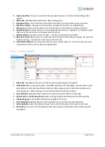
Print status window 


1.


Status bar

 indicating current print-job file as well as percentage of completion. 

2.


Print Control

 lets you pause the print. CAUTION: Pausing is not immediate 

 printer will carry out 

pre-buffered G-code command before full stop. After pausing, Duet retains all coordinates and 

print progression. After pausing, “Pause” button becomes “Resume” button.


3.


Layer Statistics

 will gather data related to current print-job and plot it in the graph. 

4.


Speed Factor

 and 

Extrusion Factor

 allows to change speed and extrusion rates while printing. 

5.


Z Baby Stepping

 controls offset along Z-axis (height of the print). 

6.


File Information

 displays data Duet can read from the G-code file currently uploaded. 

7.


Collected Data

 shows information of Layer Time and Print Duration of the current print-job. 

8.


Estimations

 uses current print speed to assess file progress and estimated time remaining until 

completion. 

Summary of Contents for BOD2-444

Page 1: ...Instruction Manual Original Version BOD2 444 3D Construction Printer Generation 02...

Page 2: ...e the commissioning 11 3 1 8 Limits of machinery 11 3 2 Machine information 12 3 3 Safety information 13 3 3 1 Signs 13 3 3 2 Safety functions 14 4 Definitions 18 4 1 Technical terms and abbreviations...

Page 3: ...ent 40 7 2 2 2 Test end stops 40 7 2 3 3 Test Load cells 40 7 2 4 4 Test pump controller OPTIONAL only if pump controller is attached 41 7 2 5 5 Test all E stops 41 7 2 6 6 Test downwards pinch safety...

Page 4: ...ance task No 2 Error Bookmark not defined 8 1 3 3 Maintenance task No 3 Error Bookmark not defined 8 1 4 4 Maintenance task No 4 Error Bookmark not defined 8 1 5 5 Maintenance task No 5 Error Bookmark...

Page 5: ...n Manual Original Version Page 5 of 50 2 Identification 2 1 Supplier information Manufacturer COBOD International A S Address Dronningens Tv rgade 26 DK 1302 K benhavn K Phone 45 70 60 55 33 E Mail ad...

Page 6: ...Instruction Manual Original Version Page 6 of 50 2 2 Declaration of Conformity...

Page 7: ...built to customer specifications The BOD2 printer works in 3 dimensions with the print head moving on the X axis the X axis bar moving on the Y axis and the whole XY group moving up and down on the 4...

Page 8: ...Instruction Manual Original Version Page 8 of 50 Figure 1 Model of printer...

Page 9: ...X axis 3 Power connection and circuit breaker 16 X carriage E Box 4 Emergency stop 17 Status lamp 5 Z1 carriage 18 X carriage 6 Z2 axis 19 Material hopper 7 Hose management 20 Mixing shaft 8 Z2 Carri...

Page 10: ...ccept any liability what so ever for subsequent loss or damage Proper use shall be deemed to include The observance of all references of this instruction manual The observance of service intervals and...

Page 11: ...e machine Automatic mode used to move the machine based on G code The machine can be operated manually The machine is operated from a web interface or from a touch panel The supply disconnector is ins...

Page 12: ...height m 10 1 x 12 6 x 10 5 Weight kg 5023 Power consumption A 32 Voltage V 3x400VAC PE Frequency Hz 50 60 Hz Short circuit current Ikmin A 500 Short circuit current Ikmax A 1200 Max speed X Axis mm s...

Page 13: ...s Mandatory When working with fresh concrete or dry mix concrete in or outside printing area Protective gloves Mandatory When working with fresh concrete or dry mix concrete in or outside printing are...

Page 14: ...the machinery shall be inspected in order to detect the reason for actuation Components included in the safety function Input part Logical part Output part Emergency stop push button E stop The emerge...

Page 15: ...emergency stop function is constructed as a Category 3 PL d Speed monitoring of the movement of the X axis and the Print head optional The speed monitoring of the movement of the X axis and the print...

Page 16: ...servo drives is 20 years The servo drives are located in the control cabinet Displays and alarms When the door is open the status will appear on the operator monitor Door open running with reduced sp...

Page 17: ...e beyond 20 years is conditional to the fact that the relevant components are replaced by new components of identical or improved properties than the original ones The safety controllers are located i...

Page 18: ...ion and depositioning of material Nozzle The small piece that sits on the end of the print head that shapes the final form of the extruded material Can be 3D printed or machined Origo The starting pos...

Page 19: ...lifting equipment and the appropriate lifting points Only instructed and certified personnel have the permission to move machine parts using a fork lift truck or crane Only appropriate and certified...

Page 20: ...section covers installation of Anchors serving as a base for securing Z axes to the ground plane The procedure involves precisely mapping and marking where the anchors will be placed drilling holes a...

Page 21: ...s acceptable and will be adjusted to by later assembly 9 Drill marked anchor holes with M8 drill Make sure the holes are vertical 10 Drill anchor holes with M18 bit to a depth of 145mm 11 Finally clea...

Page 22: ...lar to the ground Personnel installing Z axes must wear safety helmets steel toe shoes and gloves Figure 4 Placement of Z axes Tools needed Figure 5 Lifting and mounting details 1 x Crane or telescope...

Page 23: ...ntly switching between one below and one above in order to maintain correct angle 10 Repeat for each column 5 4 1 3 Mounting Y axis Tools needed Figure 6 Bracket mounts placement 1 x Crane or telescop...

Page 24: ...that safeguards are not installed in the ends of the Y axes 2 Lift the axis so it is levelled horizontally as in Error Reference source not found 3 Align the wheels and cogs on X axis with the rails...

Page 25: ...9 Electrical connectors 1 x Large flathead screwdriver Procedure 1 Locate all the cable connectors and sockets on the machine 2 See the markings on connectors to identify correct socket 3 Connect all...

Page 26: ...ng cables Parts must be stored assembled in modules and raised from ground with i e pallets or joists in such a manner that it is possible to access under using fork lift or wrap lifting strap around...

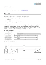
Page 27: ...s 5 6 Repacking Transport of the BOD2 printer must be done in 8 parts 1 X beam including X and Y carriages 2 Y beams 4 Z beams Including Z carriages and E box Printhead including cables Transport on t...

Page 28: ...other end to the operator computer 2 Set your computer ethernet to static IP address 192 168 0 100 3 Open a browser window i e Google Chrome and connect to Duet3D Web interface via default IP 192 168...

Page 29: ...t head and axes can be moved manually using the buttons under the machine control panel in the web interface X axis movement Positive direction to the right when standing in front of the machine Dista...

Page 30: ...VOID DAMAGE TO THE EXTRUDER PUMP NEVER RUN THE EXTRUDER IN A DRY STATE I E WITHOUT CONCRETE OIL OR WATER IN THE HOPPER If a dry run is required please remove the mixing shaft inside the material hoppe...

Page 31: ...performing as expected 4 Prepare material a Use either a manual mixer a cyclone mixer or a mixing pump i e m tec Duomix 2000 b Ensure that the material has the right consistency and water amount befo...

Page 32: ...panel to manually move the machine find the IP of the machine to connect and access and print files from the local file storage 6 1 4 2 Duet3D web Interface Duet web interface is the preferred contro...

Page 33: ...PCP unit 11 User Defined Macros Lists all macros created under the tab Macros under main menu of Duet 7 Macros can be run at any time during operation 6 1 4 2 2 Print status window 1 Status bar indic...

Page 34: ...rence documentation can be found at https duet3d dozuki com Wiki G code 6 1 4 3 1 Move and positioning commands G1 Xnnn Ynnn Znnn Ennn Fnnn Move to position Xnnx Ynnn Znnn while extruding Ennn amount...

Page 35: ...he correct distance to the floor and reset the Z homing position to this coordinate G29 Probe printing area Using a predefined mesh grid the printer will move around the printing area and probe the di...

Page 36: ...ct iii Save Save COBOD project iv Save as save COBOD project as v Export toolpath Export toolpath to directory vi Quit b Display i View mode ii Show Hide features iii Zoom c Tools i Measure curves Mea...

Page 37: ...e it is split into smaller segments b Lower head extrusion The amount of material to pre feed when printhead is moving down after a travel move Used to avoid gaps in concrete between layers and segmen...

Page 38: ...or is connected and engaged Use key switch in door to access print area 6 4 Accessories 1 M tec Duo mix 2000 optional a Available as add on purchase Used to continuously supply concrete to printhead h...

Page 39: ...to be carried out according to the following plan The operator must have read and understood this instruction manual before the maintenance of the machine is initiated When specific tasks require the...

Page 40: ...ion 6 1 2 1 Move X axis Left Right Repeat for Y axis Forward Backward 2 Move Z axis Up Down 3 Move extruder axle Extrude Retract 4 Rotate U axis rotational nozzle Clockwise Counter clockwise Overserve...

Page 41: ...unit and put it into the ground 3 Turn on pump on m tec control board 4 Pump should run until a load is put onto the material hopper 5 Load can be applied by pumping water into the printhead Observe...

Page 42: ...7 Test safety door Optional if safety door is installed and connected While machine is in operational mode signal lamp is green WARNING Never close the safety door while personnel are inside the worki...

Page 43: ...erstood this instruction manual before any maintenance and cleaning of the machine is commenced If specific tasks require the use of personal protective equipment this must be complied with For the do...

Page 44: ...c Thoroughly clean using high pressure water or similar Material hopper inside and outside Use the excess valve located on bottom Extruder pump run clean water through pump until outlet water is clean...

Page 45: ...sassemble rotational nozzle parts Check for material buildup hardened concrete and clean if necessary Check state of bearings and clean replace if necessary Check state of rubber belt and replace if n...

Page 46: ...it breaker on main E box 3 Turn key clockwise 90 deg to override safety 4 Turn on machine 5 Manually move Z axis upwards Z 200 using web control 6 Turn off machine 7 Turn key Counter Clockwise 90 deg...

Page 47: ...have read and understood this instruction manual before the maintenance of the machine is commenced If specific tasks require the use of personal protective equipment the requirement must be complied...

Page 48: ...Instruction Manual Original Version Page 48 of 50 E Mail ad cobod com...

Page 49: ...Oil and other liquids must be drained off the machine and treated separately according to local regulation Switchboards motors cables and other electronics must be demounted and treated separately ac...

Page 50: ...Instruction Manual Original Version Page 50 of 50 10 Logbook...

Reviews: