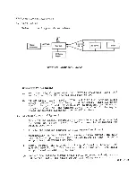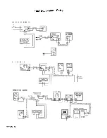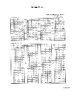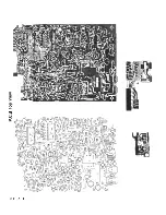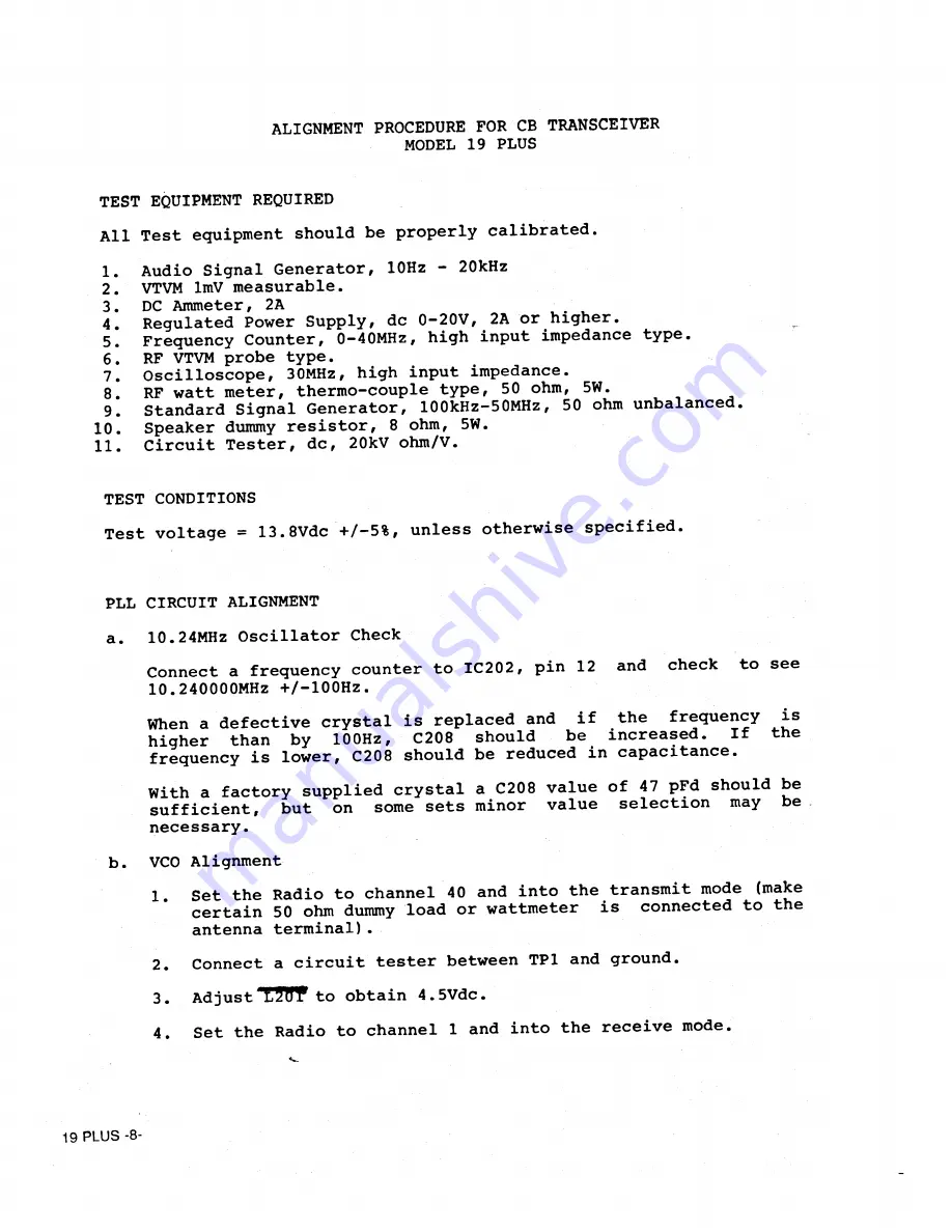
ALIGNMENT PROCEDURE FOR CB TRANSCEIVER
MODEL 19 PLUS
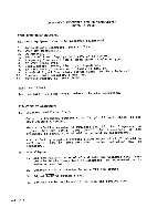
TEST EQUIPMENT REQUIRED
All Test equipment should be properly calibrated.
1.
Audio Signal Generator, 10Hz - 20kHz
2.
VTVM 1mV measurable.
3.
DC Ammeter, 2A
.
4.
Regulated Power Supply, de 0-20V, 2A or higher,
5.
Frequency Counter, 0-40MHz, high input impédance type.
6.
RF VTVM probe type.
7.
Oscilloscope, 30MHz, high input impédance.
8.
RF watt meter, thermo-couple type, 50 ohm, 5W.
9.
Standard Signal Generator, 100kHz-50MHz, 50 ohm unbalanced.
10.
Speaker dummy resistor, 8 ohm, 5W.
11.
Circuit Tester, de, 20kV ohm/V.
TEST CONDITIONS
Test voltage = 13.8Vdc +/-5%, unless otherwise specified.
PLL CIRCUIT ALIGNMENT
a.
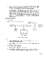
10.24MHz Oscillator Check
Connect a frequency counter to IC202, pin 12 and check to see
10.240000MHz +/-100HZ.
When a defective crystal is replaced and if the frequency is
higher than by
100Hz,
C208
should
be increased.
If the
frequency is lower, C208 should be reduced in capacitance.
With a factory supplied crystal a C208 value of 47 pFd should be
sufficient,
but on some sets minor value sélection may be
necessary.
b.
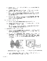
VCO Alignment
1.
Set the Radio to channel 40 and into the transmit mode (make
’
certain 50 ohm dummy load or Wattmeter is connected to the
antenna terminal).
2.
Connect a circuit tester between TPI and ground.
3.
Adjust 1 2 W to obtain 4.5Vdc.
4.
Set the Radio to channel 1 and into the receive mode.
19 PLUS -8-
Summary of Contents for 19 Plus
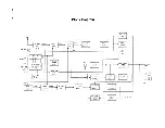
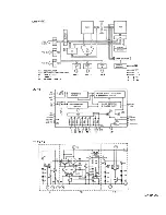
Page 7: ...19 PLUS 6 Block Diagram ...
Page 8: ... z smd 61 T X 26 PLL Circuit Block Diagram ...
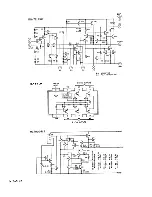
Page 15: ...ß CÛ 19 PLUS 14 ...
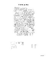
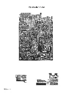
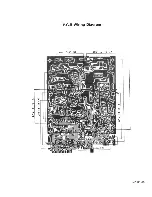
Page 17: ...P C B Bottom View 19 PLUS 16 ...
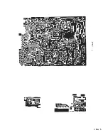
Page 18: ...401377 с 19 PLUS 17 40I06S ...
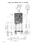
Page 25: ...Exploded View 19 PLUS 24 ...


