

IMPORTANT NOTE:
Levelling the bed is an extremely important step and if it is not done correctly every time, your
prints will fail or be of poor quality
Before you begin to level the Heated Print Bed:
Ensure the springs on all 4 corners of the Heated Print Bed are tightened all the way to the bottom by turning each
thumbwheel anti-clockwise until you can no longer turn them. This reduces the distance between the 2 plates of the print
bed to a minimum. Wipe the top of the Heated Print Bed with a clean, lint-free cloth to ensure no dust particles or other
objects are on the Heated Print Bed
Check the Z axis alignment. The X rail (holding the Extruder) should be parallel to the Heated Print Bed. If it is not, manually
rotate individual z-axis stepper motors on the bottom of both shafts to adjust. Place a Hex Wrench on the z-axis rod and
run it across the Heated Print Bed to check the z-axis is aligned horizontally
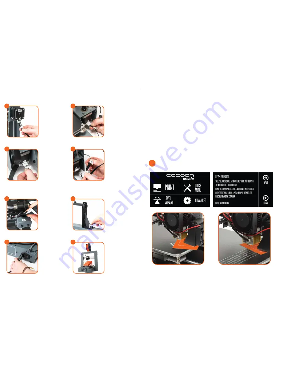
Press ‘Level Wizard’ on the touch screen panel and follow the steps as indicated
NOTE:
The distance between the Heated Print Bed and nozzle should be approximately 0.1mm
LEVELLING THE PRINT BED
CONSTRUCT AND CONNECT (CONT.)
Insert the long cable
connector marked ‘A’ into
the motor connector of the
Extruder Tower marked ‘A’
Insert the short cable
connector marked ‘B’ into
the motor connector of the
Extruder Tower marked ‘B’
3
4
Insert the black connector
marked ‘D’ into the black
connector of the Extruder
Tower marked ‘D’
Insert the white connector
marked ‘C’ into the motor
connector of the Extruder
Tower marked ‘C’
5
6
Insert one end of the black
cable connector marked ‘E’
into the black connector of
the Extruder Tower marked
‘E’. Insert the other end to the
black connector marked ‘E’
into the black connector on
the side of the Heated Print
Bed marked ‘E’
Attach the upper arm of
the filament spool holder
by unscrewing the end cap,
then reattaching. Position the
Filament Spool Holder Stand
on top of the Extruder Tower,
then insert the bolts and
tighten with the Hex Wrench
7
8
Ensure the power switch is in
the OFF position, then insert
the Power Supply Cable into
the back of the 3D Printer
Base. Insert the other end into
a nearby mains power outlet.
Turn on the power outlet, then
turn on the power switch at
the back of the 3D Printer
Base
Wait for the printer to initialise,
with the home screen shown
on the Touch Screen.
You have successfully setup
your Cocoon 3D Printer Touch
9
10
1
.


