Page 15 of 16
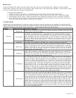
All lightbars are thoroughly tested prior to shipment. However, should you encounter a problem during installation or during the life of the
product, follow the guide below for troubleshooting and repair information. If the problem cannot be rectified using the solutions given below,
additional information may be obtained from the manufacturer – contact details are at the end of this document.
Problem
Possible Cause(s) Comments / Response
No Power
Faulty wiring
Ensure power and ground connections to the lightbar are secured. Remove and reconnect the
red power wire to the vehicle battery.
Input Voltage
The lightbar is equipped with an over voltage lockout circuit. During a sustained overvoltage
event, the Lightbar Controller inside will maintain communication with the rest of the Matrix net-
work, but disable power out to the light modules. Look for the solid red V_FAULT LED. Ensure
that input voltage does not exceed the specified range for your particular model. When overvolt
-
age occurs, the input must temporarily drop ~1V below the maximum limit in order to resume
normal operation.
Blown fuse
The lightbar may have blown an upstream fuse. Check and replace fuse if necessary.
No Communication
Ignition input
An ignition wire input is first required to bring the central node out of a sleep state. From that
point, the central node controls the status of all other Matrix compatible devices, including the
lightbar. If the lightbar is active, you should see a flashing green STATUS LED on the Lightbar
Controller inside. See the installation manual of the customer selected central node for further
troubleshooting of the ignition input.
Connectivity
Ensure that the lightbar communications cable is securely connected back to a central node.
Ensure that any other cables connecting Matrix compatible accessory devices in a CAT5 daisy
chain are fully seated with positive lock. Remember that the PRI-1 jack at the central node
must first be used, before the SEC-2 jack can be used.
Bad Light Module
No Response
If a light module is powered, but not actively communicating on the network, it should default
to error flash mode. This error flash is 200msec on, and 200msec off, and is not synchronized
with any other light module in the lightbar. So, for example, if the user activates a flash pattern,
and all the modules are participating correctly except one, then that particular module should
be in error flash mode. Note that each light module is connected to the network with a black /
white twisted pair cable. If any single connection point in the twisted pair sequence between
light modules has come loose, all downstream modules will operate in error flash mode. When
powered, this allows the user to quickly identify the offending light module(s) and/or a possible
wiring issue. Verify that the twisted pair cable connections are secure at the back of each mod-
ule. Otherwise, see manual 920-0738-00 Serial Light Module Replacement for further instruc-
tions. This should be included when you receive replacement modules.
Short Circuit
If a light module is shorted out, and the user attempts to activate a flash pattern, the pattern will
not operate. Instead, the Lightbar Controller inside the lightbar will display a solid red I_FAULT
LED. To determine which module is shorted out, remove power to the lightbar and then remove
the red wire at the back of each light module except one. Reconnect power to the lightbar, and
ensure that the device has re-established active communication with the central node. Activate
a flash pattern once more. If the single, connected light module operates properly, leave the
pattern running and proceed to reconnect the red wire at the back of all the other light modules,
one at a time. When you have reconnected the shorted module, the flash pattern will stop and
the solid red I_FAULT LED will appear once more on the Lightbar Controller. See manual 920-
0738-00 Serial Light Module Replacement for further instructions. This should be included when
you receive replacement modules.
Troubleshooting:
Maintenance:
Occasional cleaning of the lenses will ensure optimum light output. Take care when cleaning lenses. Although very impact resistant,
polycarbonate scratches easily. Clean the lens and base with soap and water or a lens polish using a microfiber or other lint free soft cloth.
Do not use solvents as they may damage the polycarbonate.
Lens Removal and Installation:
1. Identify the lens(es) to be removed - not all lenses need to be removed to access the internal components.
2. Unfasten the retaining clips from the lens(es) of the lightbar. Set these aside, as they will be used to reattach the lens(es).
3. Carefully lift the lens off the seal – choose a suitable location to temporarily store the lens so as to not scratch the surface.
4. When reinstalling, gently apply pressure around the upper lens taking care not to damage the seal around the lower lens set.
Reattach the retaining clips to fasten the upper lens to the lightbar.


