background image

4

ca2051 rev B. 2011 Audiovox Electronics Corporation. All rights reserved.

10 Pin Main Harness

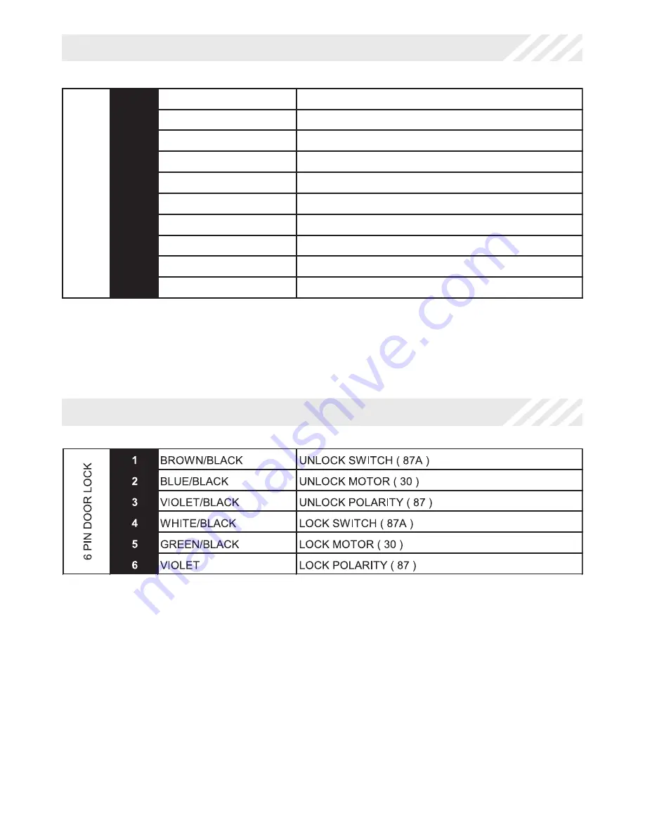
6 Pin  Door Lock Harness

1

BLUE/GREEN

2ND UNLOCK OUTPUT ( - )

2

BLACK/WHITE

ILLUMINATED ENTRY OUTPUT ( - )

3

WHITE/RED

PARKING LIGHT INPUT

4

WHITE 

PARKING LIGHT OUTPUT

5

BLACK

GROUND

6

ORANGE

GROUND WHEN ARMED OUTPUT ( - )

7

RED

BATTERY 12V ( + )

8

BROWN/BLACK

HORN OUTPUT ( - )

9

YELLOW

IGNITION INPUT ( + )

10

RED/WHITE

TRUNK RELEASE OUTPUT ( - )

10 PIN MAIN

Summary of Contents for ca 2051

Page 1: ...1 ca2051 rev B 2011Audiovox Electronics Corporation All rights reserved PROFESSIONAL SERIES Remote Keyless Entry Installation Guide ca 2051 ...

Page 2: ...n Main Harness 5 6 Pin Door Lock Harness 8 Additional Ports 9 LED Port 9 Programming Port 9 Set Up Programming 10 Transmitter Programming 10 Manual Feature Programming 10 Programming Feature Banks 11 Chirp Delete User Accessible 11 Feature Descriptions 12 Transmitter Button Functions 13 System Layout 14 Table of Contents ...

Page 3: ...res near hot surfaces Avoid mounting components or routing wires near moving parts Tape or loom wires under hood for protection and appearance Technical Support 800 421 3209 or go to http techservices codesystems com Use a Digital Multi Meter for testing and verifying circuits DO NOT USE A TEST LIGHT OR COMPUTER SAFE PROBE as these can set off air bags or damage vehicle computers Use grommets when...

Page 4: ...ock Harness 1 BLUE GREEN 2ND UNLOCK OUTPUT 2 BLACK WHITE ILLUMINATED ENTRY OUTPUT 3 WHITE RED PARKING LIGHT INPUT 4 WHITE PARKING LIGHT OUTPUT 5 BLACK GROUND 6 ORANGE GROUND WHEN ARMED OUTPUT 7 RED BATTERY 12V 8 BROWN BLACK HORN OUTPUT 9 YELLOW IGNITION INPUT 10 RED WHITE TRUNK RELEASE OUTPUT 10 PIN MAIN ...

Page 5: ...ers positive voltage when the parking lights are turned on Positive switching Parking Lights Connect the WHITE RED wire to a 15 Amp max fused battery source Connect the WHITE wire to the parking light output wire Negative switching Parking Lights Connect the WHITE RED wire to a good chassis ground Connect the WHITE wire to the parking light output wire 2 BLACK WHITE ILLUMINATED ENTRY OUTPUT This w...

Page 6: ...he ignition switch Connect the RED wire to the constant 12 Volt battery wire NOTE Remove all fuses until all connections are made 5 BLACK GROUND Connect the BLACK wire to a solid chassis ground point using a ring terminal and self tapping screw not supplied Scrape away paint from the grounding point to ensure a good connection The recommended grounding point is a metal surface in the driver s side...

Page 7: ...urned to the ON or RUN position The voltage does not drop out when the key is turned to the START or CRANK position Connect the YELLOW wire to the vehicle s Ignition wire 10 RED WHITE TRUNK RELEASE OUTPUT Locate the vehicle s trunk release wire at the trunk release switch Verification This wire will register either positive voltage or ground when the trunk release is activated This is a low curren...

Page 8: ...E BLACK wire to the wire that provides a ground signal from the factory door unlock switch to the factory door lock control relay Connect the VIOLET and the VIOLET BLACK wires to a solid chassis ground point The WHITE BLACK and BROWN BLACK wires are not required for this type of door lock unlock system 3 Wire Positive Switched Door Locks Connect the GREEN BLACK wire to the wire that provides a 12 ...

Page 9: ...he drill will not damage any existing components as it passes through the panel Drill a 1 4 hole and pass the red and blue wires from the LED through the hole from the front of the panel Firmly press the body of LED into the hole until fully seated Additional Ports Programming Valet Button Port Select a mounting location that is within reach of the ignition switch as this switch in combination wit...

Page 10: ...ON 2 Press and hold the valet override button 3 Within 10 seconds the system will chirp 3 three times 4 Press 1 button of each transmitter you wish to program 5 The system will respond with 1 chirp for each accepted transmitter 6 Pressing the override button at anytime during programming will advance to the next bank NOTE The system will exit transmitter programming after 15 seconds of inactivity ...

Page 11: ...k 2 4 Chirps Security Control 1 LED Flash 2 LED Flash 3 LED Flash 4 LED Flash 5 LED Flash 1 Silent Choice ON OFF Feature Bank 3 5 Chirps Output Control 1 LED Flash 2 LED Flash 3 LED Flash 4 LED Flash 5 LED Flash 1 Extended Lock Pulse 1 Second 3 5 Seconds 1 Second Lock Double Pulse Unlock 30 Second Lock Double Pulse Unlock Double Pulse Lock 1 Second Unlock 2 2nd Unlock Output 2nd Unlock Factroy Dis...

Page 12: ...3 5 Seconds Single 3 5 second lock pulse single 3 5 second unlock pulse 1 Second Lock Double Pulse Unlock Single 1 second lock pulse double 1 second unlock pulse 30 Second Lock Double Pulse Unlock Single 30 second lock pulse double 1 second unlock pulse Double Pulse Lock 1 Second Unlock Double 1 second lock pulse single 1 second unlock pulse 2 2nd Unlock Output Controls the timing of the BLUE GREE...

Page 13: ... the RED WHITE trunk release output wire when trunk release is activated from the transmitter Push and Hold Output is continuously active until transmitter button is released 10 Seconds Output stays active for 10 seconds regardless of length button press on transmitter 20 Seconds Output stays active for 20 seconds regardless of length button press on transmitter Latched until IGN ON Output stays a...

Page 14: ...INPUT WHITE PARKING LIGHT OUTPUT BLACK GROUND ORANGE ARMED OUTPUT RED BATTERY 12V BROWN BLACK HORN OUTPUT YELLOW IGNITION INPUT RED WHITE TRUNK RELEASE OUTPUT BROWN BLACK UNLOCK SWITCH 87A BLUE BLACK UNLOCK MOTOR 30 VIOLET BLACK UNLOCK POLARITY 87 WHITE BLACK LOCK SWITCH 87A GREEN BLACK LOCK MOTOR 30 VIOLET LOCK POLARITY 87 PROGRAMMING VALET PORT LED PORT CA 2051 ...

Page 15: ...15 ca2051 rev B 2011Audiovox Electronics Corporation All rights reserved ...

Page 16: ...C rules and with RSS 210 of Industry Canada Operation is subject to the following two conditions 1 This device may not cause harmful interference and 2 This device must accept any interference received including any interference that may cause undesired operation Warning Changes or modifications not expressly approved by the party responsible for compliance could void the user s authority to opera...

Reviews: