Code Blue
•
259 Hedcor Street
•
Holland, MI 49423 USA
•
800.205.7186
•
www.codeblue.com
GU-149-AA
page 48 of 63
CB 2 Series
Administrator Guide
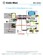
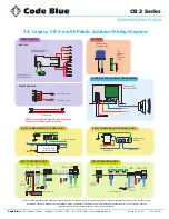
27 Legacy CB 2-a Wiring Diagram
(prior to 2020)
Product wiring diagram shown reasonably represents current offering and is intended to assist in component identifi cation and service. Earlier product
production may have different components and wiring connections. Reference the model and serial number from the unit ID tag and contact
manufacturer to confi rm replacement part version and availability.
FULL FILENAME
C:\USERS\MRUUD.CODEBLUE\APPDATA\LOCAL\MICROSOFT\WINDOWS\
TEMPORARY INTERNET FILES\CONTENT.OUTLOOK\EHKAOED2\CB2A WIRING
DIAGRAM-B.VSD
SIZE
FSCM NO
DWG NO
REV
DRAWN
Mike Rose
CB-2a Wiring Diagram
B
ISSUED
7/22/16
SCALE
1 : 1
7/26/2016
SHEET
3 OF 3
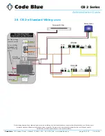
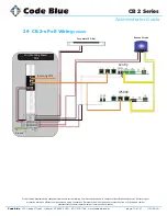
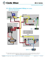
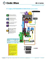
Revised date
in
out
GRD
Fro
nt
Pa
ne
lD
isc
on
ne
ct
High Voltage
Power
Option
Customer
Provided
Power
Option
(12
–
24 Volts
AC or DC @ 12 watts nominal)
PoE
Power
Option
LAN 2
LAN 1
WAN
PoE
PAS
Control
Aux ports
PAS
Audio
+ -
+ -
IP5000 VoIP
IA4100 Analog
PAS
Control
Aux Outputs
1
2
3
N.O.
N.C.
Aux
Inputs
PAS
Audio
12VDC or
Battery
Main
Power
E
th
ern
et
POTS line - PSTN
Data +PoE
DATA
Data Cat5e
100
–
240Vac / 0.5A
277Vac /0.2A
to
12Vdc 3.3A
Class 2
Neutral
Load
S-180-1224-LED
FP-LED Bar
Fuse’s
Beacon Strobe
1 Amp
FP LED Light
0.5 or 1Amp
IP5000
1 Amp
IA4100
1.5 Amp
in
out
GRD
PoE Cat5e Source
Cat5e
Non PoE - Cat5e
PoE splitter
powered
12VDC or
Battery
Main
Power
AC to DC
PoE Power (DC)
Low Voltage12- 24V AC - DC

