background image

Code Blue


 259 Hedcor Street 

 Holland, MI 49423 USA 

 800.205.7186 

 www.codeblue.com

GU-149-B

page 21 of  33

CB 2 Series

Administrator Guide

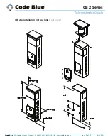
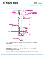
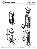
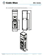
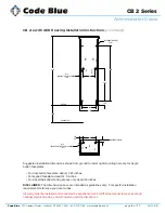
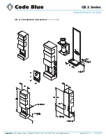
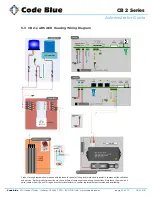
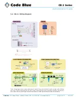
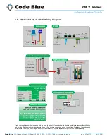
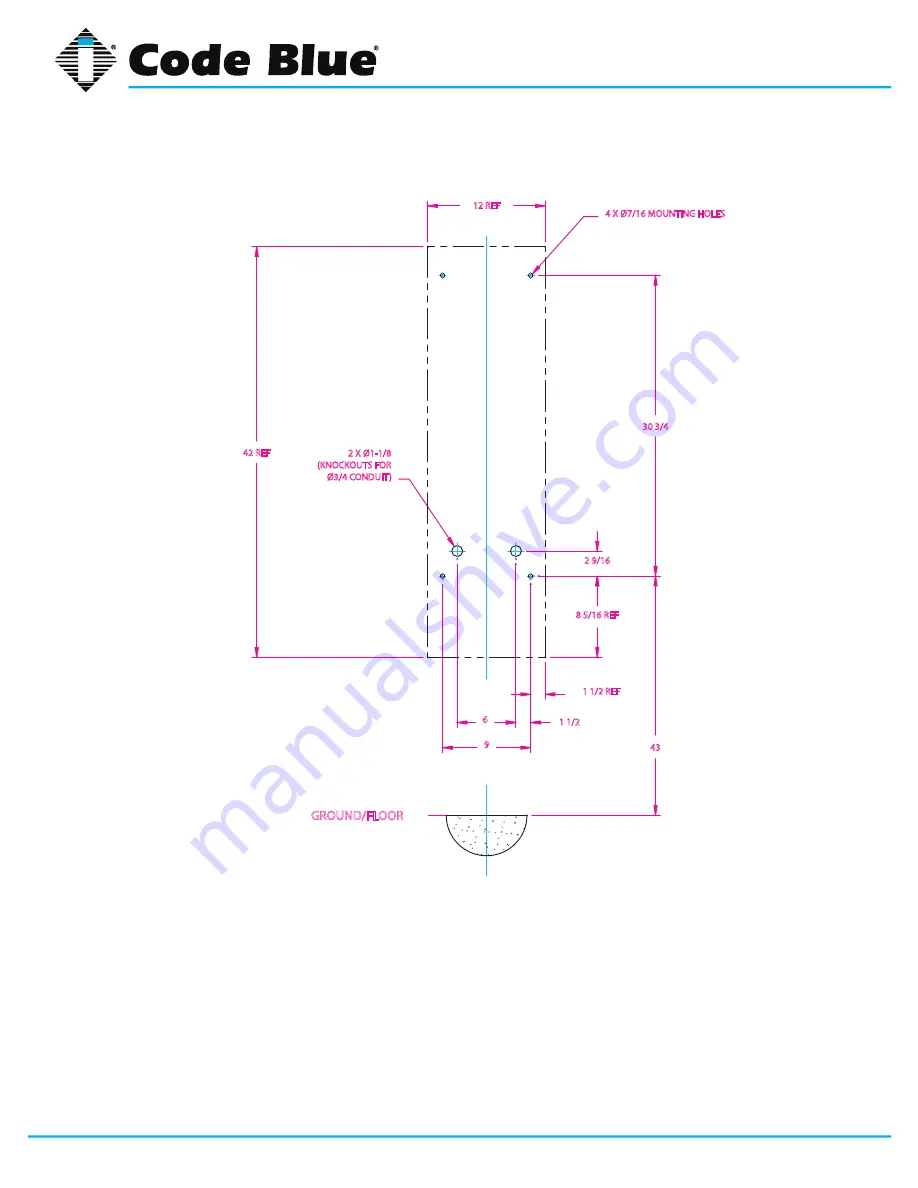
CB 2-s Installation Instructions 

(continued)

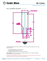
Suggested installation dimensions shown from ground to lower right mounting hole are for single 

button faceplates.

• 

For dual button faceplate, deduct 3.25 inches.

• 

For keypad faceplate, deduct 4.5 inches.

• 

For wheelchair direct facing access only, deduct 6 inches.

DISCLAIMER: 

The dimensions above are intended as guidelines only.  For specific installation 

requirements reference your local codes.

All wiring must be installed and connected by experienced and certified personnel to meet local and 

national electrical codes, and will include a service disconnect.

30 3/4

43

2 9/16

6

1 1/2

12 REF

9

GROUND/FLOOR

4 X Ø7/16 MOUNTING HOLES

2 X Ø1-1/8

(KNOCKOUTS FOR 

Ø3/4 CONDUIT)

42 REF

8 5/16 REF

1 1/2 REF

Summary of Contents for CB 2-e

Page 1: ...800 205 7186 www codeblue com Administrator Guide Installation Setup CB 2 Series CB 2 e CB 2 e with AED Housing CB 2 e with Public Address CB 2 s...

Page 2: ...CB 2 e Installation Instructions 9 4 2 CB 2 e with Public Address Installation Instructions 13 4 3 Cb 2 e with AED Housing Installation Instructions 16 4 4 CB 2 s Installation Instructions 19 4 5 Pole...

Page 3: ...urable construction our wall mount units can meet any requirement or purpose All 2 Series units have a rugged steel construction shat terproof Lexan Lens industrial engineering grade reflective graphi...

Page 4: ...s own phone line or PBX extension Multiple units shall not be supported 3 Speakerphones require programming before operation Consult the User Guide or Administrator Guide enclosed with the unit or go...

Page 5: ...33 CB 2 Series Administrator Guide 3 1 CB 2 e Replacement Parts List Part Part Number LED Strobe Light 40159 Button Head Security Screws 3 pack 41418 Analog Phone Line Surge Suppressor 41471 IP Phone...

Page 6: ...B 2 e with Public Address Replacement Parts List Part Part Number LED Strobe Light 40159 Button Head Security Screws 3 pack 41418 Analog Phone Line Surge Suppressor 41471 IP Phone Line Surge Suppresso...

Page 7: ...umber LED Strobe Light 40159 Button Head Security Screws 3 pack 41418 Analog Phone Line Surge Suppressor 41471 IP Phone Line Surge Suppressor 41421 Manifold R B 5 way 40101 Power Brick 120V 240V 277V...

Page 8: ...ries Administrator Guide 3 4 CB 2 s Replacement Parts List Part Part Number LED Strobe Light 40159 Button Head Security Screws 3 pack 41418 Analog Phone Line Surge Suppressor 41471 IP Phone Line Surge...

Page 9: ...Consult an ADA specialist in your area to verify local and federal guidelines 3 Drill all marked holes 4 Install the housing Four anchors of appropriate size and type should be used to fasten the hou...

Page 10: ...tory default settings 1 IP Address 192 0 0 64 2 Camera is accessed on IP Port 8000 3 User Name admin 4 Password 12345 For additional support contact HIKVISION at 1 Website http www hikvision usa com s...

Page 11: ...Code Blue 259 Hedcor Street Holland MI 49423 USA 800 205 7186 www codeblue com GU 149 B page 11 of 33 CB 2 Series Administrator Guide CB 2 e Installation Instructions continued...

Page 12: ...or single button faceplates For dual button faceplate deduct 3 25 inches For keypad faceplate deduct 4 5 inches For wheelchair direct facing access only deduct 6 inches DISCLAIMER The dimensions above...

Page 13: ...ral guidelines 3 Drill all marked holes 4 Install the housing Four anchors of appropriate size and type should be used to fasten the housing to the wall IMPORTANT If wiring is being supplied from the...

Page 14: ...Code Blue 259 Hedcor Street Holland MI 49423 USA 800 205 7186 www codeblue com GU 149 B page 14 of 33 CB 2 Series Administrator Guide CB 2 e with Public Address Installation Instructions continued...

Page 15: ...hole are for single button faceplates For dual button faceplate deduct 3 25 inches For keypad faceplate deduct 4 5 inches For wheelchair direct facing access only deduct 6 inches DISCLAIMER The dimens...

Page 16: ...sabilities Act ADA of 1990 the speakerphone button s should be positioned between 34 and 48 inches from grade level Consult an ADA specialist in your area to verify local and federal guidelines 3 Dril...

Page 17: ...reet Holland MI 49423 USA 800 205 7186 www codeblue com GU 149 B page 17 of 33 CB 2 Series Administrator Guide CB 2 e with AED Housing Installation Instructions continued 11 23 06 15 5 12 53 9 00 3 00...

Page 18: ...duct 4 5 inches For wheelchair direct facing access only deduct 6 inches DISCLAIMER The dimensions above are intended as guidelines only For specific installation requirements reference your local cod...

Page 19: ...plate to the wall IMPORTANT If wiring is coming in from the back ensure that the conduit is aligned at this time 4 Reattach the light bracket 5 Reattach the outer shell Holding the shell horizontal h...

Page 20: ...Code Blue 259 Hedcor Street Holland MI 49423 USA 800 205 7186 www codeblue com GU 149 B page 20 of 33 CB 2 Series Administrator Guide CB 2 s Installation Instructions continued...

Page 21: ...nches For keypad faceplate deduct 4 5 inches For wheelchair direct facing access only deduct 6 inches DISCLAIMER The dimensions above are intended as guidelines only For specific installation requirem...

Page 22: ...has been reached when the band stops moving through the buckle 6 When maximum tension has been reached roll tool over buckle At same time reverse the handle carefully with approximately a three quart...

Page 23: ...iring Diagram Product wiring diagram shown reasonably represents current offering and is intended to assist in component identification and service Earlier product production may have different compon...

Page 24: ...UDIO AUX PORTS LAN PoE LAN 1 LAN 2 PAS CONTROL PAS AUDIO NOTE Use the supplied modular inter connects to link the unit s various powered devices Multi Tap LV fuses are generally 2A GMA AUDIO OUTPUT 12...

Page 25: ...Product wiring diagram shown reasonably represents current offering and is intended to assist in component identification and service Earlier product production may have different components and wiri...

Page 26: ...gram Product wiring diagram shown reasonably represents current offering and is intended to assist in component identification and service Earlier product production may have different components and...

Page 27: ...ing Diagram Product wiring diagram shown reasonably represents current offering and is intended to assist in component identification and service Earlier product production may have different componen...

Page 28: ...et areas Stains indicate leaking and gasket should be replaced Verify moisture weep hole on cabinet bottom is open and unobstructed Verify bottom of bollards are at least 1 2 inch above footing and fr...

Page 29: ...eactions on Code Blue units an appropriate surface maintenance schedule should be adhered to The Surface Care Frequency table below provides general guidelines to assist in configuring a schedule Plea...

Page 30: ...is time the person calling the unit can depress the 6 key on their telephone keypad which will provide access to the AED device 4 The access panel on the back of the Code Blue unit is removed and the...

Page 31: ...86 www codeblue com GU 149 B page 31 of 33 CB 2 Series Administrator Guide 7 Locating Unit Serial Numbers Remove the speakerphone faceplate with the special security bit The serial number will be list...

Page 32: ...ranty Code Blue Corporation provides a limited warranty on this product Refer to your sales agreement to establish the terms of the limited warranty In addition Code Blue s standard warranty language...

Page 33: ...om resources user guides 11 ToolVox Administrator Guide http codeblue com resources admin guides 12 ToolVox UPD Configuration Operation http codeblue com resources user guides 13 ToolVox Quick Start h...

Reviews: