Code Blue
•
259 Hedcor Street
•
Holland, MI 49423 USA
•
800.205.7186
•
www.codeblue.com
GU-163-A
page 15 of 27
CB RT
Administrator Guide
9 Overhead Camera Mount Installation Instructions
TOOLS REQUIRED
INSTALLING THE OVERHEAD CAMERA MOUNT
The camera mount will come with a gasket already mounted to the bracket on the arm. Place the
bracket over the mounting holes and insert the four 3/8-16 X 1 stainless bolts. (The 3/8” stainless
steel bolts should have one stainless steel washer and one rubber washer.) Verify the camera
mount is evenly positioned to ensure the gasket seal is properly seated. Tighten the bolts with your
3/8” wrench in a crisscross pattern to ensure even pressure until it is snug against the outside of the
enclosure.
INSTALLING THE CAMERA
Camera and wiring (supplied by others) is installed into the male 1½ NPT.
3/8
Wrench
Ladder
Access Panel
Security Bit
All wiring must be installed and connected by experienced and certified personnel to meet
local and national electrical codes, and will include a service disconnect.
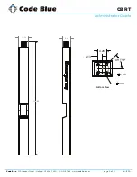
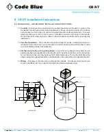
DRILL ONE
2” DIA HOLE
FOR WIRING
IN LINE WITH PIPE
51.38
2.50
1.00
A
A
B
B
C
C
D
D
4
4
3
3
2
2
1
1
XXXXXX
NEXT LEVEL
XXXXXX
CUSTOMER DWG NO.
XXXXXX
CUSTOMER
DRAWING NO.
.X ±.12 ±.030
.XX ±.06 ±.010
.XXX ±.03 ±.005
.XXXX -- ±.001
STRUCTURAL
TOLERANCES UNLESS OTHERWISE SPECIFIED
MACHINING
1:20
DRAWN BY
DESCRIPTION
DATE
3/10/2016
1
SCALE
THIRD ANGLE PROJECTION
SHEET
REV NO.
-
ANGLES ± 1°
OF 1
KH

