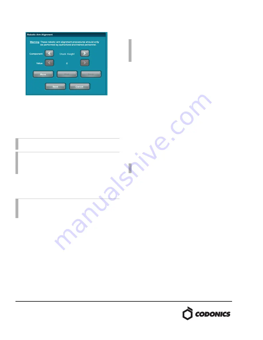
2. Select the
Stack Height
component.
3. Press the
Move
button and the robotic arm will perform
the calibration process.
Once this calibration has been set, the Stack Height
calibration setting cannot be stopped or reverted by pressing
the c
ancel
button.
aêáîÉ=eÉáÖÜí=~åÇ=mêáåí=qê~ó=eÉáÖÜí
1. Open the top cover and place a folded piece of paper or
card stock in the optical sensor as shown on the first page
of this document. This will allow access to the drives and
print tray while the cover is open.
2. Verify the User Interface shows a status of “Ready”,
indicating that the sensor is disabled.
3. Use the Component Arrows to navigate to “Top Drive
Height”.
4. Manually open the top drive and place a single disc in
the tray.
5. Press the MOVE button on the user interface. The arm
will move down and measure the height of a single disc
in the drive.
6. Remove the disc and close the top drive.
7. Repeat steps 2 through 5 substituting “Top Drive
Height” for “Bottom Drive Height” and “Print Tray
Height”.
eçêáòçåí~ä=~åÇ=sÉêíáÅ~ä=mêáåí=lÑÑëÉíë
1. Select “Printer H. Offset” and press “Print”. A disc with
crosshairs and the current horizontal and vertical offset
values will be printed.
2. Orient the disc right side up so you can read it.
3. Make adjustments to the horizontal offset as required.
4. Press “Print” again to test settings.
5. Repeat steps 3 and 4 to adjust vertical offset.
6. Once you are satified with the adjustments, press “Save”.
`~äáÄê~íáçå=ìëáåÖ=íÜÉ=_ê~îç`çãã=ríáäáíó
The steps below provide a means to manually calibrate the
pick height for the print tray and DVD drives. This process
may be required if the pick height calibration on the GUI
was attempted without a disc in the print tray or DVD drive
tray.
1. Connect a USB mouse and keyboard.
2. Minimize the UI (WD).
3. Open Windows Explorer (W E).
4. Using Windows Explorer, navigate to
C:\opt
5. Copy
codburn.yes
and paste in the same folder. This
will create a file called
Copy of codburn.yes
or
something similar.
6. Rename the resulting copy to
codburn.pause.yes
(this
keeps CodBurn from interfering with us running the
BravoComm.exe command)
7. Open a command prompt by pressing W R,
then typing
cmd
in the Windows Run dialog box.
8. Type
cd c:\opt\BravoPro_Commands
to navigate to
the proper directory.
9. If not already done, open the top cover and disable the
top cover open sensor as described in the previous
section.
NOTE:
This setting only applies to the 82-series, 83-
series, and 84-series Virtua Recorders.
CAUTION:
Performing the steps below without a disc
in the component being calibrated will incorrectly
calibrate the component and put it into a state where it
cannot be calibrated from the GUI.
CAUTION:
The robotic arm will move with the top
cover sensor disabled. Keep hands, hair, and loose
clothing clear of robotic arm when in motion.
NOTE:
If the unit has been incorrectly calibrated without
a disc in the tray, it can no longer be calibrated from the
User Interface. Use the steps outlined in the “Calibration
using the BravoComm Utility” section below to restore
functionality.
NOTE:
A Windows™ compatible keyboard and mouse
with USB cables are required for this procedure.


