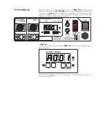
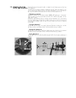
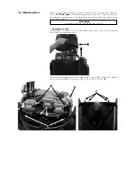

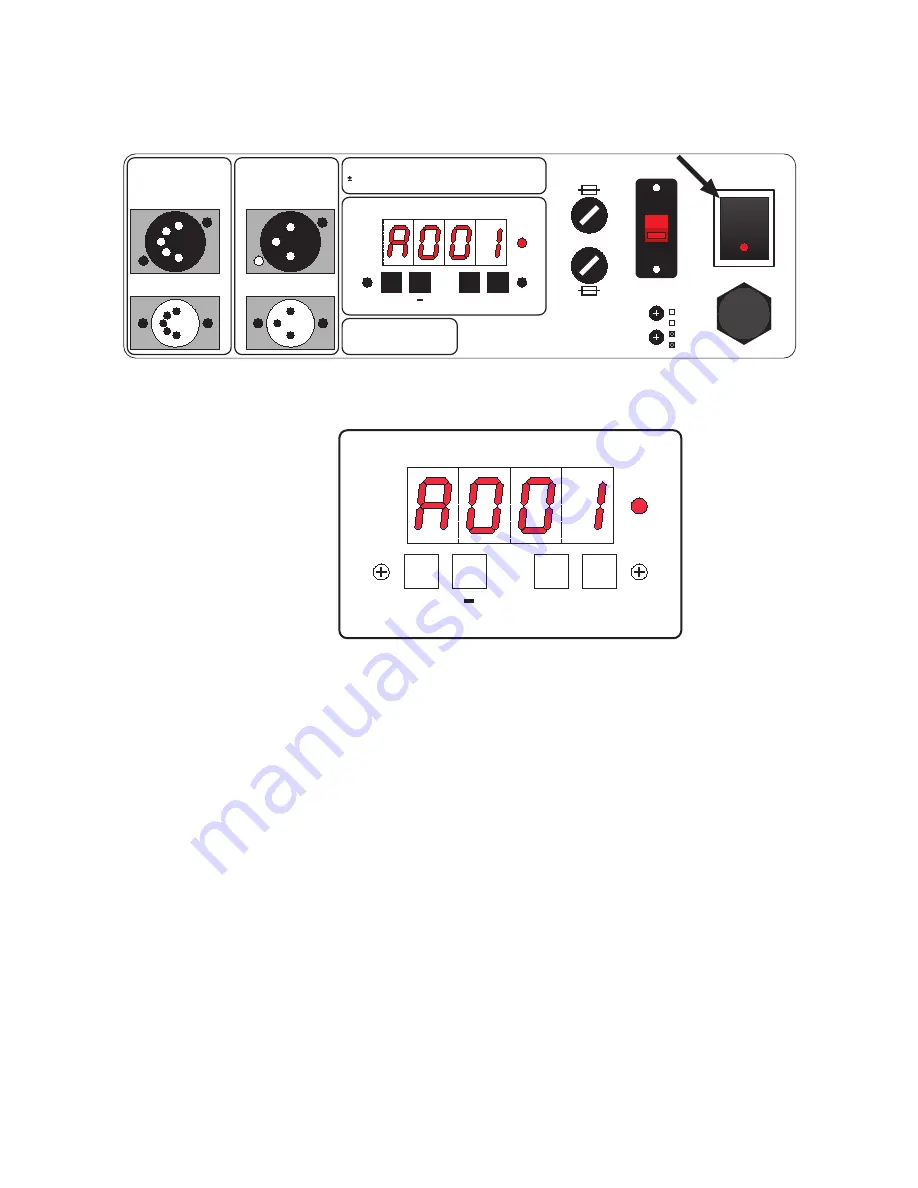
9. Powering up
After having followed the preceding steps, turn on the
DMX 512
controller which
will be used to control the
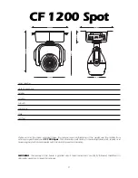
CF 1200 Spot
. Then turn on the power to the projector
and turn on the
power
switch. The projector will perform a reset function on all the
internal and external motors. This will last some few seconds, after which it will be
subject to the external signal from the controller.
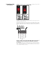
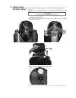
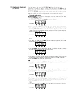
DMX led
The DMX led will be static on to indicate
DMX 512
signal is being correctly received
by the projector.
If the led is off, the projector is not receiving signal. Check the cabling and the func-
tioning of the controller.
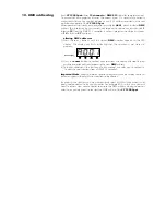
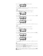
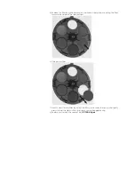
function display
DMX
menu enter
+
serial number
enter
A001
to
A499
13 channels per unit
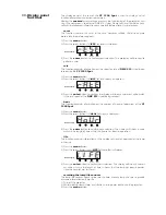
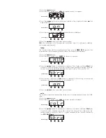
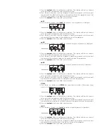
function display
DMX
menu enter
+
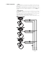
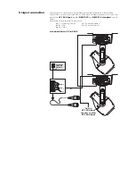
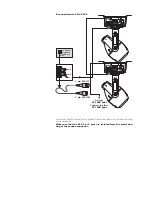
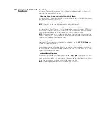
pin1: gnd
pin2: data-
pin3: data+
pin4: optional-
pin5: o
in
out
dmx 512
in
out
pin1: gnd
pin2: data-
pin3: data+
dmx 512
standard
Set dmx 512 address
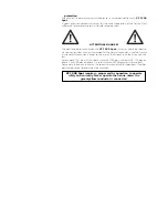
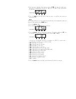
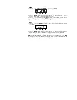
Warning!
Electronic ballast, read
instructions carefully before
installing the unit, size of
the neutral must be correct.
240V
T 2A @ 230V
T 4A @ 115V
power
T 15A @ 230V
T 25A @ 115V
coemar
set
main at:
115V
208V
230V
240V
Attenzione!
Ballast elettronico, leggete
attentamente le istruzioni prima
di installare l'apparecchio,
dimensionate correttamente il neutro.


