5
5. Menu System
The menu system and its settings are an appropriate place to commence learning how to operate the controller. After
connecting the power supply and pushing the BO button the controller will be in automatic mode. Simultaneously depress the
PAGE-UP and PAGE_DOWN buttons. The controller will enter menu mode after approximately 2 seconds.
In the top line of the display the number of the actual menu item can be read. In the bottom line of the menu the item
description is displayed. You can select between menu items using the DATA ENTRY slider or the UP-DOWN buttons. To
select a menu item, press the ENTER button. To return to automatic mode press the ESC button.
If the setup menu item is selected, the controller enters the setup menu after pressing the ENTER button. From there, further
menu items can be selected.
Menu system map:
- 1. EDIT SHAPE
(construction of 1-72 Shapes )
- 2. EDIT PROGRAM
(construction of 1-72 programs)
- 3. EDIT SEQUENCE
(construction of 1-72 sequences)
- 4. EDIT PRESET
(construction of 1-72 preset scenes)
- 5. EDIT RECORD
(construction of 1-72 records)
- 6. FUNCTION BUTTON
- 7. SETUP
- 1. UNIT INSTALL
(entering a new device into the directory (library) / modification of an existing device)
- 2. UNIT POSITION
(assigning devices to one of 16 positions in the directory / setup of mirror directions)
- 3. DISPLAY SETUP
(set display intensity and contrast)
- 5. LED SETUP
(set LED intensity)
- 6. LANGUAGE
(select the display language)
- 7. WORK TIME
(operating hours counter)
- 8. SOFTWARE VERSION
(software version number and issue date)
- 9. CONTROLLER VER.
(controller serial number and manufacturing date)
- 10. MENU CODE
(menu code setting / switch off)
MENU SYSTEM –MENU LOCK CODE
If the menu lock code is activated, the code must be entered prior to gaining access to the menu. The code can be entered via
buttons 1-24. After entering the code, press ENTER. If an incorrect code is entered, the controller will give a warning and
the ESC button must be pressed in order to recommence the process.
If you lose or forgot your code, you will need to access the PIN code of the controller. To gain access to the PIN code you
will first need the serial number of your controller. If the display panel is seeking the code, press the F7 button, and the serial
number will be visible on the upper line of the display. By contacting the manufacturer or dealer with this serial number, they
will be able to provide you with the correct PIN code for your controller.
The PIN code is also entered using the 1-24 buttons, but before you press ENTER you should press and hold down the F7
button. The controller will the skip directly to the menu system. It is recommended that you modify or delete the menu lock
code prior to escaping from menu mode.
5.1 MENU 1: SHAPE EDITING
The shape generator located in the controller allows up to 8 different shapes to be recreated by the mirrors or the moving
head of particular articulated devices, with a range of alterable parameters. These shapes can then be assigned to program
steps or preset scenes.
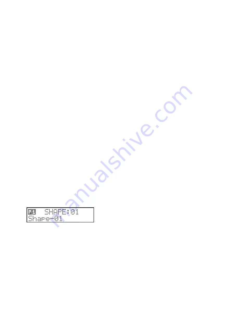
In the shape selection editor, you may select from 72 shapes using the 1-24 buttons and the PAGE shift button in
combination. In the top line of the display the available shapes are displayed. In the bottom line the corresponding name of
the selected shape is displayed. If a shape is not available, ‘empty’ is displayed.
During shape selection the respective movements are immediately visualised on any attached articulated devices.
F3 (DELETE): if a selected shape is recorded, it can be deleted
F5 (ESC): return to the menu without saving any changes.
F6 (ENTER): advance to edit the selected shape position
F7 (COPY): copy a selected shape to an empty position


