background image

A thermal sensor in the body of the 

iSpot S

protects the unit against overheating.

The thermal sensor operates by removing voltage to the lamp if the ambient temperature rises above a preset maximum due to either
less than ideal air circulation around the fixture or in the event of cooling fan failure.

Whilst every possible precaution has been taken to ensure the trouble-free operation of your 

iSpot S

, the following periodic maintenance

is highly recommended.

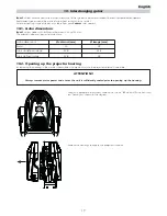
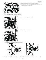
To gain access to the internals of the unit refer to section 

10.2. Opening up the projector housing

of this manual.

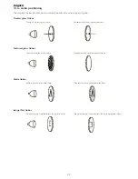
12.1. Periodic cleaning

Lenses and reflectors

Even a fine layer of dust can reduce the luminous output substantially. Regularly clean all lenses and the reflector using a soft cotton
cloth, dampened with a specialist lens cleaning solution. 

Fans and air passages

The fans and air passages must be cleaned approximately every 6 weeks; the period for this periodic cleaning will depend, of course,
upon the conditions in which the projector is operating. Suitable instruments for performing this type of maintenance are a brush and
a common vacuum cleaner or an air compressor.

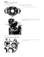
12.2. Periodic maintenance

Lamp

The lamp should be replaced if there is any observable damage or deformation due to heat. This will avoid the danger of the lamp
exploding.

Mechanicals

Periodically check all mechanical devices for wear and tear; gears, guides, belts, etc., replacing them if necessary. Periodically check the
lubrication of all components, particularly the parts subject to high temperatures. If necessary, lubricate with suitable lubricant, available
from your coemar distributor.

Electrical components

Check all electrical components for correct earthing and proper attachment of all connectors, refastening if necessary.

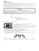
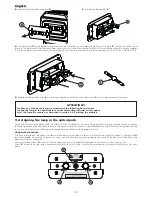
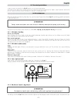
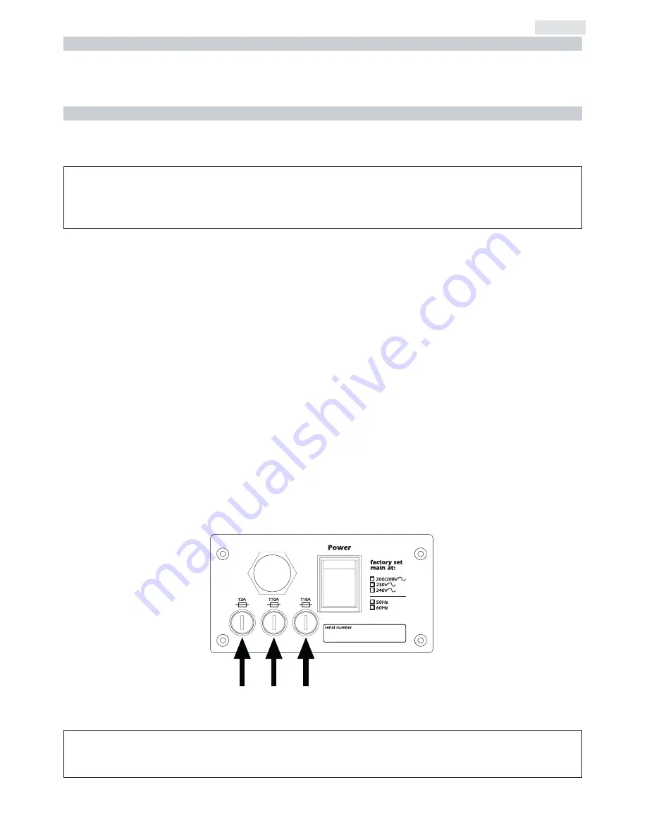
12.3. Fuse replacement

Locate the fuse, which protects the lamp and electronics, in the base of the 

iSpot S

Using a multimeter, test the condition of the fuse, replacing it with one of equivalent type if necessary.

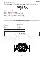
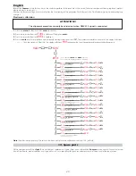
12.4. Electronic motor alignment

The display panel of the 

iSpot S

allows for the electronic alignment of the projector’s motors in the optical system. This procedure is per-

ATTENTION!!

This procedure should only be undertaken by qualified and experienced technical personnel..

ATTENTION!!

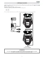
Always remove mains power and ensure the unit is sufficiently cooled prior to opening up the housing.

12. Maintenance

11 Thermal protection

23

English

Summary of Contents for i spot S

Page 1: ...manuale di istruzioni instructions manual Version 1 0 ...

Page 2: ...lease note in the space provided above the relative service information of the model and the retailer from whom you purchased your iSpot S This information will assist us in providing spare parts repairs or in answer ing any technical enquiries with the utmost speed and accuracy ATTENZIONE la sicurezza dell apparecchio è garantita solo con l uso appropriato delle presenti istruzioni per tanto è ne...

Page 3: ...enu navigation 13 8 2 Measure and test MEAS 14 8 3 Function settings FUNC 15 8 4 Rapid scrolling 15 8 5 Connecting the DR1 16 8 6 Use of RJ45 connector 16 8 7 Turning on the projector with no articulated movement 16 8 8 Resetting counters 16 9 Lamp installation and alignment Pag 17 9 1 Lamp installation 17 9 2 Aligning the lamp in the optical path 18 10 Interchanging gobos Pag 19 10 1 Gobo dimensi...

Page 4: ...rth connection is essential for proper functioning of the projector Never operate the unit without proper earth connection 5 Mains cables should not come into contact with other cables 6 Do not operate the projector with wet hands or in an area where water present 7 The fixture should never be located in an exposed position or in areas of extreme humidity A steady supply of circulating air is esse...

Page 5: ... fro your authorised coemar service centre 2 3 CE norms The projector meets or exceeds all applicable CE requirements 3 1 Technical characteristics Power 208 230 240 Vac 50 60Hz Nominal current 7 3A 230V Maximum current 9A Power factor cos ϕ 0 9 Lamp wattage 1200W Maximum ambient temperature 35 C 95 F Weight 38 Kg 83 77 Lbs IP rating IP20 3 2 Dimensions 3 3 Components Component description A Zoom ...

Page 6: ...following diagram The structure should also be sufficiently rigid so as not to move or shake whilst the projector moves during its operation Do not install the projector in locations where it is readily accessible by aunthorised or untrained personnel 4 2 Safety connections If the iSpot S is affixed to a mobile structure the use of a safety chain designed to meet relevant safety standards is recom...

Page 7: ...elow using an appropriate screwdriver thereby remov ing the cover completely and allowing access to the internal components of the base of the iSpot S Locate the transformer in the base of the unit Select a voltage from amongst 208 230 or 240V by disconnecting cable n 5 and moving it to the correct voltage Refer to the sticker located on the transformer to ensure the proper terminal is selected fo...

Page 8: ...mal operation Locate the mains cable which exits the base of the unit and connect as shown below ATTENTION The use of a thermal magnetic circuit breaker is recommended for each projector Strict adherance to all regulatory norms is higly recommended iSpot S should never be supplied mains power via a Dimmer this is potentially dangerous Prior to powering up the projector ensure that the model in you...

Page 9: ...tors Pin connections conform to the international standard as per the following table pin 1 GND pin 2 data pin 3 data If using a controller which output signal via an XLR 5 5 pin socket do not use pins 4 and 5 leave them unconnected ATTENTION Ensure that all data conductors are isolated from one another and the metal housing of the connector Pin number 1 should never be connected to the device s p...

Page 10: ...pot S features are listed in paragraph 7 2 DMX functions chart DMX addresses To ensure that each projector accesses the correct signal it is necessary to correctly address each fixture This procedure must be carried out on every projector being used When powered up initially each projector will show A001 which indicates DMX address 001 a projector thus addressed will respond to commands on channel...

Page 11: ...thproportionalincreaseinspeed 193 255 76 100 9 9 zoom proportional proportional control of zoom from wide beam to narrow 0 255 0 100 10 10 focus proportional proportionalcontroloffocus 0 255 0 100 nogobo 0 10 0 4 gobo1 11 40 4 16 gobo2 41 70 16 27 gobo3 71 100 28 39 gobo4 101 130 40 51 gobo5 131 160 51 63 gobo6 161 192 63 75 proportional continuousrotationofthegobowheelfromslowtofast 193 255 76 10...

Page 12: ...proportional proportionalcontrolofthepercentageofcyancolourinthelightbeam from 0 to 100 0 255 0 100 22 20 magenta proportional proportionalcontrolofthepercentageofmagentacolourinthelight beam from 0 to 100 0 255 0 100 23 21 yellow proportional proportional control of the percentage of yellow colour in the light beam from 0 to 100 0 255 0 100 step nocolourtemperaturecorrection openbeam6500 K 0 10 0...

Page 13: ... to be pushed to obtain the desired function 8 1 Quick guide to menu navigation For your convenience the following is a guide to navigating the menu system of the projector F U NC enter MEAS enter PDIR o TDIR o OPTO o FANS o DISP o LED o RESE o OFSE o DEMO o IRIS o PAN o ID o TEMP o V FAN o DMIN o RATE o ALRM o HOUR o AOO1 menu TEST o A023 new DMX address o A023 DMX address 23 select new DMX addre...

Page 14: ... o P A N pan movement enter es 0 1 50 enter 0128 enter enter o T I L T tilt movement enter es enter enter enter o D I M M dimmer activation enter es enter enter enter o S H U T shutter activation enter es enter SURE enter enter S T O R to record the position of the unit and of its internal components If DMX signal is not applied the recorder setting will appear at the end of reset operation when t...

Page 15: ...g Function without pan tilt o o o o o o o o o o enter DEMO flashing demo program activation PDIR pan movement inversion To reverse horizontal movement direction of the beam on DMX level variation TDIR tilt an movement inversion To reverse vertical movement direction of the beam on DMX level variation OPTO optic sensor de activation To deactivate the optic sensor function with return inpo sition of...

Page 16: ...the connection of DR1 the remote control that allows to supply the display to upgrade the software and to access to all the functions that are usually selectable from the DR1 For more information pls Read the manual of the different devices 8 7 Turning on the projector with no articulated movement This function may be useful should you need to power up the iSpot S whilst it is in its flight case o...

Page 17: ...o attempting removal The fixture should be allowed to stand and cool for 10 minutes prior to its removal The lamps are part of the mercury vapour family of discharge lamps and must be handled with great care The lamp operates at high pressure and the slight risk of explosion of the lamp exists if operated over its recommended life We recommend therefore that the lamp be replaced within the manufac...

Page 18: ...ignment procedure The lamp should be on black out and dimmer fully open and no colours selected If the lamp is not correctly aligned a hot spot will be readily noticeable Using the 3 adjusters in unison you will need to bring the hot spot to the centre of the beam and then flatten the beam to maximum uniformity Unscrew the two knobs A move it until the correct vertical and horizontal alignement is...

Page 19: ... dimensions are 10 2 Opening up the projector housing By removing the housing in the manner shown below compete access to the projector s internals is possible Using an appropriate screwdriver remove the screws A which affix the front and rear housings as shown in the diagram Remove the housings to expose the projector s internals ATTENTION Always remove mains power and ensure the unit is sufficie...

Page 20: ...rews B as shown in this diagram 3 Remove the gobo group as shown in the diagram You will the gobo wheels in a position where access to the individual gobos is quite straightforward Proceed with the changing of the individual gobos as required 10 4 Replacing gobos on gobo wheel 1 1 Use a tool such as a screwdriver as a lever on the spring C on the inside of the gobo wheel 20 English ...

Page 21: ...5 Replacing gobos on gobo wheel 2 1 Use a screwdriver to loosen the screw D 2 Sliding the lever towards the top On the opposite side yo will note an opening as shown in figure At this point proceed as per previous section Replacing gobos on gobo wheel 1 Ultimate the gobos substitution sliding the lever in the opposite direction in order to close up the opening and retighening screw D 21 English ...

Page 22: ... lamp Untreated side facing the projector front Textrued glass Gobos Textured side facing the lamp Smooth side facing the projector front Metal Gobos Reflective side facing the lamp Treated side facing the projector front Image Test Gobos Positive image readable text facing the lamp Negative image reversed text facing the projector front 22 English ...

Page 23: ...mmon vacuum cleaner or an air compressor 12 2 Periodic maintenance Lamp The lamp should be replaced if there is any observable damage or deformation due to heat This will avoid the danger of the lamp exploding Mechanicals Periodically check all mechanical devices for wear and tear gears guides belts etc replacing them if necessary Periodically check the lubrication of all components particularly t...

Page 24: ...28 enter o es 0130 enter 0128 enter o es 0125 enter 0128 enter o es 0135 enter 0128 enter o es 0132 enter 0128 enter o es 0127 enter 0128 enter o es 0 1 2 1 enter 0128 enter o es 0140 enter 0128 enter o es 0127 enter 0128 enter o es 0127 enter 0128 enter o es 0127 enter A001 enter 0128 enter o es 0127 enter 0128 enter o es 0127 enter 0128 enter o es 0127 o o o o o o o o o o o o o o o o o o RESE AO...

Page 25: ...e 5 rear motors located in the rear of the body when viewed from the rear of the unit Sensor is continuously reading the magnet Check the cabling and the RESET sensors the motors and the integrity of the connecting belts S4ER Control circuit error relating to position sensors controlling the 5 front motors located in the front of the body when viewed from the rear of the unit Sensor is continuousl...

Page 26: ...the display shows the message LAER The lamp may have reached the end of its life The lamp is not installed The lamp circuit protection fuse may be blown Disconnect mains power and check the lamp condition checking the lamp life display Disconnect mains power and install a lamp Check with your coemar service centre prior to replacing the fuse The lamp turns off intermittently The projector is too h...

Page 27: ...2 A 46042 Castel Goffredo Mantova Italy ph 39 0376 77521 fax 39 0376 780657 info coemar com Coemar si riserva il diritto di apportare modifiche senza preavviso Coemar reserves the right to effect modifications without notification ...

Reviews: