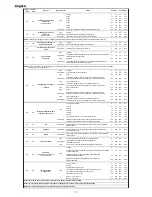


formed by
Coemar
at the factory. It may be useful to perform this procedure in the case of internal components being replaced (motors,
electronic parts, sensor, ecc.).
Altering the factory settings may radically alter the functioning of the projector. Carefully read all of the following prior to attempting any
changes.
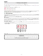
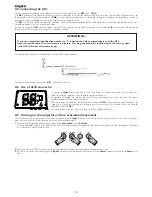
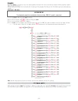
Electronic calibration
1.
Press the
menu
button and then
enter
to confirm.
2.
Press the
+
or
-
button until
FUNC
is displayed. Then press
enter.
3.
Press the
+
or
-
button until
RESE
is displayed.
4.
Press the
enter
and menu buttons simultaneously, holding them for at least
10"
. The motors will perform a reset and the display will show
-
- -- -- --
for a few seconds. After this, the display will show
PAN
confirming that you have entered electronic calibration mode.
Note:
Simultaneously pressing the
+
and
-
buttons will return the calibration value to 128 (default).
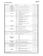
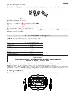
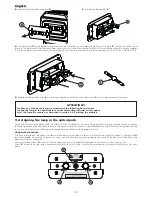
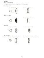
All the components of the
iSpot S
are available as replacement spares from your authorisded
Coemar
service centre. Accurate descrip-
tion of the fixture, model number, and type will assist us in providing for your requirements in an efficient and effective manner.
13. Spare parts
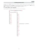
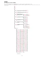
PAN
pan alignment
pan movement alignment
☞
enter
0 1 2 8
☞
enter
☞
+
o
–
es.
0 1 2 0
☞
enter
0 1 2 8
☞
enter
☞
+
o
–
es.
0 1 2 0
☞
enter
0 1 2 8
☞
enter
☞
+
o
–
es.
0 1 2 0
☞
enter
0 1 2 8
☞
enter
☞
+
o
–
es.
0 1 4 0
☞
enter
0 1 2 8
☞
enter
☞
+
o
–
es.
0 1 3 0
☞
enter
0 1 2 8
☞
enter
☞
+
o
–
es.
0 1 2 5
☞
enter
0 1 2 8
☞
enter
☞
+
o
–
es.
0 1 3 5
☞
enter
0 1 2 8
☞
enter
☞
+
o
–
es.
0 1 3 2
☞
enter
0 1 2 8
☞
enter
☞
+
o
–
es.
0 1 2 7
☞
enter
0128
☞
enter
☞
+
o
–
es.
0 1 2 1
☞
enter
0128
☞
enter
☞
+
o
–
es.
0 1 4 0
☞
enter
0128
☞
enter
☞
+
o
–
es.
0 1 2 7
☞
enter
0128
☞
enter
☞
+
o
–
es.
0 1 2 7
☞
enter
0128
☞
enter
☞
+
o
–
es.
0 1 2 7
☞
enter
A 0 0 1
☞
enter
0128
☞
enter
☞
+
o
–
es.
0 1 2 7
☞
enter
0128
☞
enter
☞
+
o
–
es.
0 1 2 7
☞
enter
0128
☞
enter
☞
+
o
–
es.
0 1 2 7
☞
+
o
–
☞
+
o
–
☞
+
o
–
☞
+
o
–
☞
+
o
–
☞
+
o
–
☞
+
o
–
☞
+
o
–
☞
+
o
–
☞
+
o
–
☞
+
o
–
☞
+
o
–
☞
+
o
–
☞
+
o
–
☞
+
o
–
☞
+
o
–
☞
+
o
–
☞
+
o
–
RESE
AOO1
☞
+
o
--
FUNC
☞
+
o
--
☞
menu
TILT
tilt alignment
tilt movement alignment
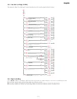
DIMM
dimmer alignment
Alignment of dimmer
SHUT
shutter alignment
Alignment of shutter
COLR
color wheel alignment
color
wheel alignment
ZOOM
zoom alignment
alignment of zoom
FOCU
focus alignment
focusing lens alignment
GOB1
gobo wheel 1 alignment
gobo wheel 1 alignment
GOB2
gobo wheel 2 alignment
gobo wheel 2 alignment
GB P 1
gobos alignment
rotating gobos alignment on gobo wheel 1
(the one nearest to the lamp)i
GBP2
gobos alignment
rotating gobos alignment on gobo wheel 2
EF CT
frost prisms alignment
frost and prisms wheel alignment
IRIS
iris alignment
iris diaphragm alignment
CYAN
cyan alignment
cyan filter alignment
MAGE
magenta alignment
magenta filter alignment
YELL
yellow alignment
yellow filter alignment
COMV
CTO alignment
CTO filter alignment
END
end
To end the electronic motor calibration
procedure and to record it
Press together
enter
and
menu
keys for
10 seconds: the display will show this menu
ATTENTION!!
The alignment procedure can only be carried out when DMX 512 signal is connected.
24
English


