background image

Panorama Power MK2

may operate in two modes:

1.

Using DMX 512 signal 

2.

In automatic “STAND ALONE” or “MASTER/SLAVE” (see section 

8.0 Automated functions

)

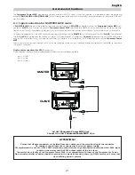
6.1. Connecting DMX signal

Control signal is digital and is transmitted via two pair screened ø0.5mm cable as per international standards for the transmission of
DMX512 data. Connection is serial, utilising XLR 3 male and female sockets located on the base of the 

Panorama Power MK2. Coemar

supplies XLR3 connectors with a IP67 protection rating. In order to preserve the protection rating of the 

Panorama Power MK2

, use

only similarly rated connectors for signal transmission and reception.

Plug/socket connections for XLR3

connectors:

Pin connections conform to the international standard as per the following table:

pin 1 = GND           
pin 2 = data -   
pin 3 = data +

If using a controller which output signal via an XLR 5 (5 pin) socket, do not use pins 4 and 5, leave them unconnected.

ATTENTION!!

Ensure that all data conductors are isolated from one another and the metal housing of the connector.

Pin number 1 should never be connected to the device’s power supply. 

We recommend the use of an XLR3 DMX terminating connector 

5 pin XLR 5/M

3 pin XLR 3/F

in

out

out

in

Controller
DMX 512

OUT

3

2

1

Ad altri 

Panorama Power MK2

Connect to other 

Panorama Power MK2

60Hz

alto/top

60Hz

alto/top

6. DMX signal functions

13

English

Summary of Contents for Panorama Power MK2

Page 1: ...manuale di istruzioni instructions manual Version 1 0 Panorama Power MK2 ...

Page 2: ... in the space provided above the relative service information of the model and the retailer from whom you purchased your Panorama Power MK2 this information will assist us in answering any technical enquiries with the utmost speed and accuracy ATTENZIONE la sicurezza dell apparecchio è garantita solo con l uso appropriato delle presenti istruzioni per tanto è necessario conservarle WARNING the sec...

Page 3: ...ng DMX signal 13 6 2 Powering up 14 6 3 DMX addressing 14 6 4 DMX functions 15 7 Display panel functions Pag 16 7 1 Quick guide to menu navigation 16 7 2 Operating mode MODE 17 7 3 Measure and test MEAS 18 7 4 Function settings FUNC 19 7 5 Rapid scrolling 20 7 6 Connecting the DR1 20 8 Automated functions Pag 21 8 1 Signal connection for MASTER SLAVE mode 21 8 2 MASTER SLAVE mode 22 8 3 STAND ALON...

Page 4: ...f technology inherent in the Panorama Power MK2 requires the use of specialised personnel for all service applications refer all work to your authorised coemar service centre 4 A good earth connection is essential for proper functioning of the projector 5 Mains cables should not come into contact with other cables 6 Do not operate the projector with wet hands Safety 1 The projector should always b...

Page 5: ... authorised coemar service centre 2 3 CE norms The projector meets or exceeds all applicable CE requirements 3 1 Technical characteristics Power 208 230 240 Vac 50 60Hz Nominal current 7A Maximum current 9A Power factor cos ϕ 0 8 Lamp wattage 2 x 575W MH Maximum ambient temperature 35 C 95 F Weight 47 5 Kg 104 5 lbs Protection rating IP44 3 2 Dimensions 3 3 Components The principle components of t...

Page 6: ...m When hanging the unit we recommend the use of the optional support accessory cod 9821 to which clamps may be attached as indicated at B in the diagram below The support accessory allows the unit to be rotated through 360 Do not install the projector in a location where it may be interfered with by people who are not familiar with the instructions contained in this manual ATTENTION Always ensure ...

Page 7: ...re Ensure that the safety chain being used is of a sufficient rating to hold the weight of the unit 4 3 Beam adjustment The angle of inclination of the Panorama Power MK2 may be adjusted to ensure that the beam is pointing in the required direction To alter the inclination proceed with the following instructions 1 Loosen the knobs D on the sides of the projector body 2 Adjust the inclination to su...

Page 8: ...is switched off or its dimmer is fully on The following pictures indicate the correct procedure for replacing the various diffusion filters 1 Using a suitable tool remove the two fasteners G which affix the filters 2 Remove the filter H currently in position 3 Insert the appropriate filter to suit the beam dimensions you wish to achieve Select from filter which alter different diffusion patterns a...

Page 9: ...cate the procedure needed to adjust the barndoors 1 Use a suitable tool to loosen the screws L which fasten the barn doors in position 2 Position the barndoors to achieve the required effect 3 After adjustment ensure that the fasteners are securely tightened to ensure that the barndoors remain in the desired position Filter type Horizontal beam angle Vertical beam angle 1 Diffusion filter cod VT13...

Page 10: ...pond to those in use in your country of operation you may alter the settings as described in the following paragraphs The required voltage and frequency adjustments must be made on both the ballast lamp power and the transformer electronics power 1 Using an appropriate tool remove the 8 screws A located on the side of the projector which affix the base cover 2 Remove the base cover B B A ATTENTION...

Page 11: ...d voltage Refer to the sticker on the transformer to ensure correct selection is made 7 When you have made the necessary changes reposition and refasten the covers and screw as per their original position To ensu re that the fixtures protection rating is maintained ensure that the cover is fitted and seated correctly and the screws tightened firmly avoiding damage to the silicone seal ATTENTION Ca...

Page 12: ...e mains cable which exits the base of the unit and connect as shown below ATTENTION The use of a thermal magnetic circuit breaker is recommended for each projector Strict adherance to all regulatory norms is higly recommended Panorama Power MK2 should never be supplied mains power via a Dimmer this is potentially dangerous Prior to powering up the projector ensure that the model in your possession...

Page 13: ...imilarly rated connectors for signal transmission and reception Plug socket connections for XLR3 connectors Pin connections conform to the international standard as per the following table pin 1 GND pin 2 data pin 3 data If using a controller which output signal via an XLR 5 5 pin socket do not use pins 4 and 5 leave them unconnected ATTENTION Ensure that all data conductors are isolated from one ...

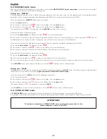
Page 14: ...X addresses Upon first powering up the display will show A001 indicating DMX address 001 a projector thus addressed will respond to com mands on channel 1 to 6 from your DMX controller A second unit should be addresses as A007 a third as A013 and so on until the final projector has been addressed Altering DMX addresses 1 Press the or buttons until the display shows the required DMX address The cha...

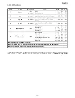
Page 15: ... 0 100 4 yellow proportional proportional yellow control from white to yellow 0 255 0 100 park nofunction 0 10 0 4 right lamp off 11 29 4 11 park nofunction 30 140 12 55 right lamp on 141 255 55 100 park nofunction 0 10 0 4 left lamp off 11 29 4 11 cmy reset once only 30 135 12 53 cmy and dimmer reset once only 136 170 53 67 park nofunction 171 240 67 94 left lamp on 241 255 95 100 decimal percent...

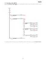
Page 16: ...lections NOTE the symbol shows which key has to be pushed to obtain the desired function 7 1 Quick guide to menu navigation For your convenience the following is a guide to navigating the menu system of the projector AOO1 MODE o o menu enter o o SL MA DMX DMIN VOLT RATE ALRM HOUR o o o o enter MEAS FUNC LAMP enter FANS o DISP o LED o RESE o OFSE o TEST o DIMM o COLR o ID o Press together enter and...

Page 17: ...ions AOO1 MODE menu enter o o enter SL slave function Slave unit SL enter MA master function Master unit PRG 1 Example program 1 enter PROGprogram To select the number of program to run o o o PALL all programs PRG4 to program PRG1 from program enter enter enter enter WAIT waiting time Waiting times among memories sec 0 1 from number 0460 to number o enter enter enter DMX DMX function DMX function ...

Page 18: ...the DC main voltage in volt You must consider normal the values between 26V and 36 V enter RATE DMX rate Reading of DMX512 signal value enter 24 value reading NDMX no dmx signal ALRMalarm Reading of warning message sequences errors shown after reset operation enter NO AL no alarm ADER warning message 10 value reading HOUR Working time Working time hour enter o LIFE Visualisation of lamp life time ...

Page 19: ...ds AA DISP reverse display Reverse reading display depending on mounting position ground mounted or suspended enter o enter enter LED display control To disable display visualisation ON display actived AUTO display switch off after 6 second press any key to re activate it enter enter enter enter ID ID number setting To set the unit s ID number from 1 to 250 1 250 numeric value enter DFSE default f...

Page 20: ...up truss structures to gain direct physical access to the projector to alter such parameters as DMX address reading outputs such as lamp life setting master slave configurations as well as all other functions available via the digi tal display unit on the projector In order to utilise the DR1 remote device you must first activate the identifying number ID of the projector which must be unique in t...

Page 21: ...similarly rated connectors so as to preserve the IP protection rating of the Panorama Power MK2 Should you wish to connect in excess of 10 units we recommend the use of a suitable opto isolated splitter and amplifier to retransmit the signal as required Plug socket connections for XLR3 connectors Pin connections conform to the international standard as per the following table pin 1 GND pin 2 data ...

Page 22: ...e display Press the enter button 8 Press the or button to select the wait time between steps then press the enter button If you wish to alter the speed of the colour changes 9 Press the enter button The display will show PROG 10 Press the or button until SPEE is shown in the display Press the enter button 11 Press the or button to select the speed at which you wish to have the colour change occur ...

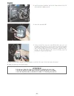
Page 23: ...of explosion of the lamp exists if operated over its recommended life We recommend therefore that the lamp be replaced within the manufacturer s specified lamp life 9 1 Lamp installation 1 Use a suitable tool to remove the 14 screws A which affix the rear hou sing B of the projector 2 Remove the rear housing B of the projector with the handle provided ATTENTION Disconnet the unit from mains power ...

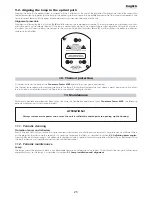
Page 24: ...p s packaging The GX 9 5 lampbase is symmetrical in con struction DO NOT USE UNDUE FORCE In case of difficulty re read the instructions and repeat the procedure 7 Replace the lampholder assembly in its original position and refasten the screws which were previously removed 8 Repeat the procedure for the second lamp ATTENTION Each time you change the lamp we recommend the following be carried out r...

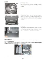
Page 25: ...r less than ideal air circulation around the fixture or in the event of cooling fan failure Whilst every possible precaution has been taken to ensure the trouble free operation of your Panorama Power MK2 the following periodic maintenance is highly recommended 11 1 Periodic cleaning Protection lenses and reflectors Even a fine layer of dust can reduce the lumious output substantially and alter bea...

Page 26: ... necessary a liquid deter gent solution Mechanicals Periodically check all mechanical devices for wear and tear gears guides belts etc replacing them if necessary Periodically check the lubrication of all components particularly the parts subject to high temperatures If neces sary lubricate with suitable lubricant available from your coemar distributor Check that the bolts which affix the barndoor...

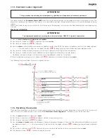
Page 27: ...ion on lamp life To do this you will need to access the calibration menu see section 11 4 Electronic motor alignment The following are the required steps 1 Press the menu button and then press enter 2 Press the or buttons until FUNC is displayed Confirm this by pressing enter 3 Press the or buttons until RESE is displayed 4 Press the menu and enter buttons simultaneously hodling them pressed for a...

Page 28: ...nit to your authorised coemar service centre to have the EEPROM check and possibly replaced ADER DMX ADDRESS Error The projector is not receiving all DMX channels needed to operate correctly Check the DMX address indicated on the display and the channel numbers being outputted from the controller Note that not all controllers will output all 512 channels ER20 ER99 SYSTEM Error Turn the unit off an...

Page 29: ...2 A 46042 Castel Goffredo Mantova Italy ph 39 0376 77521 fax 39 0376 780657 info coemar com Coemar si riserva il diritto di apportare modifiche senza preavviso Coemar reserves the right to effect modifications without notification ...

Reviews: