background image

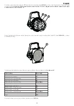
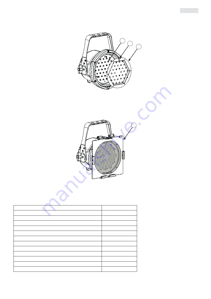
To further increase the beam angle the 

“R”

flood reflector is available (code 

CO9168

) and it must be fitted instead of the lenses group

and filter holder. 

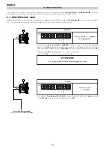
For the user of IR remote control: ensure that the “N” slot is aligned on the reflector where the IR sensor

is located on the side of led disc “H”.

To vary the wideness of the beam without opening the unit, it’s possible to install an external filter holder 

“T”

(code 

CO9169/1

), as shown

on following drawing.

The following table details the range of beam angle and diffusion filters available for the 

Par Lite Led IP

.

To shape the beam you can use an external barndoor (code 

CO9164

).

Optical group

Beam angle

Narrow Lenses (standard)

12°

Narrow Light Frost Filter

17°

Narrow Frost Filter

25°

Narrow Strip Frost Filter

Beam Shake

Medium Lenses (cod. 9167)

30°

Medium Light Frost Filter

35°

Medium Frost Filter

45°

Medium Strip Frost Filter

Beam Shake

Flood 

130°

S

H

N

R

9

English

Summary of Contents for par lite LED IP

Page 1: ...manuale di istruzioni instructions manual Version 1 1 par lite LED IP ...

Page 2: ...ded above the relative service information of the model and the retailer from whom you purchased your Par Lite Led IP this information will assist us in providing spare parts repairs or in answering any technical enquiries with the utmost speed and accuracy ATTENZIONE la sicurezza dell apparecchio è garantita solo con l uso appropriato delle presenti istruzioni per tanto è necessario conservarle W...

Page 3: ... 2 Mains connection 10 6 DMX signal functions Pag 11 6 1 Connecting DMX signal 11 6 2 Turning on the projector 11 6 3 DMX addressing 12 6 4 DMX functions 12 7 Test function Pag 13 8 Light ON function Pag 13 9 Auto function Pag 14 9 1 Master Slave mode 14 9 2 Stand Alone mode 15 10 IR function Pag 16 10 1 Master Slave mode IR 16 10 2 Stand Alone mode IR 17 11 DR1 function Pag 17 11 1 Functions usin...

Page 4: ...l 3 The level of technology inherent in the Par Lite Led IP requires the use of specialised personnel for all service applications refer all work to your authorised Coemar service centre 4 A good earth connection is essential for proper functioning of the projector Never operate the unit without proper earth connec tion 5 The mains cable should not come into contact with other cabling 6 Never hand...

Page 5: ... C 95 F Weight 3 6 Kg 7 9 lbs IP rating IP66 3 2 Dimensions 3 3 Projector components The principal components of the Par Lite Led IP are shown in the diagram below Descrizione dei componenti 1 Rear panel 2 Projector body 3 Dip switch panel 4 Led control PCB 5 Switching power supply 6 Head 7 Lens group 8 Front frame 212mm 8 35 202mm 7 95 268mm 10 55 211mm 8 30 268mm 10 5 167mm 6 46 3 Product specif...

Page 6: ... a lighting truss or similar we recommend the use of appropriate clamps B affixed to the yoke in the holes A provided as shown in the following diagram Never install the fixture in a position in an accessible position to personnel who may ignore or be unaware of the safety directions men tioned in this manual ATTENTION Always ensure that your support structure and fixings bolts clamps etc are rate...

Page 7: ...chain both suitably rated for the purpose 4 3 Adjusting beam direction The Par Lite Led IP can be tilted to adjust the beam output To perform this adjustment follow the instructions set out below 1 Loosen the handle D located on the side of the projector thus allowing the inclination to be changed 2 Adjust the projector s tilt 3 Refasten the handle D on the side of the projector 240 200 D C C 7 En...

Page 8: ...that can be fitted either internally or externally to the unit The standard optical group fitted on Par Lite Led IP is composed by a group of lenses that gives 12 beam angle Here following you will find instructions to install different optical groups 1 Open the unit as shown on paragraph 4 4 Open and close the unit 2 Remove the 3 screws G 3 Replace the lenses L and ensure that the led of H disc f...

Page 9: ...tall an external filter holder T code CO9169 1 as shown on following drawing The following table details the range of beam angle and diffusion filters available for the Par Lite Led IP To shape the beam you can use an external barndoor code CO9164 Optical group Beam angle Narrow Lenses standard 12 Narrow Lenses Light Frost Filter 17 Narrow Lenses Frost Filter 25 Narrow Lenses Strip Frost Filter Be...

Page 10: ...f a suitable rating 230 240V 0 2 amps constant current 208V 0 25 amps constant current 100 115V 0 5 amps constant current Locate the mains cable which exits the base of the unit and connect as shown below ATTENTION The use of a thermal magnetic circuit breaker for each fixture is recommended Strict adherence to regulatory norms is strongly recommended Par Lite Led IP should not be powered through ...

Page 11: ... the XLR3 connectors Connection is to international standards Connection is as indicated below pin 1 GND pin 2 data pin 3 data Should your DMX 512 controller output signal via a cannon XLR5 5 pin pins 4 and 5 should remain unconnected 6 2 Powering up After having followed the preceding steps turn on mains power on to the unit The POWER led located near the dip switch panel will come on Turning on ...

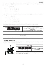
Page 12: ...trolofthepercentageofbluecolourfrom0to100 0 255 0 100 step noeffect 0 9 0 4 proportional variable speed strobing effect from slow to fast 10 57 4 22 step stopstrobe 58 59 23 23 proportional sequencedpulseeffect slowclosing fastopening variable speed pulsing from slow to fast 60 108 24 42 step stopstrobe 109 110 43 43 proportional sequencedpulseeffect fastclosing slowopening variable speed pulsing ...

Page 13: ...set to ON ON 256 auto test light on DR1 1 2 4 8 16 32 64 128 IR dip switch 1 dip switch 2 dip switch 4 Red on off off illumination level 20 off on off illumination level 30 on on off illumination level 40 off off on illumination level 50 on off on illumination level 60 off on on illumination level 80 on on on illumination level 100 dip switch 8 dip switch 16 dip switch 32 Green on off off illumina...

Page 14: ... position and selecting a program for it to follow by making a selection from the following dip switches 1 2 4 8 256 There are 4 programs which can be select ed dip switches 1 2 4 8 select programs 1 2 3 and 4 respectively dip switch 256 runs all four programs sequentially To configure a Par Lite Led IP as SLAVE is simply a matter of setting the Auto dip switch to the ON All other dip switches sho...

Page 15: ...Par Lite Led IP as STAND ALONE simply set dip switch Auto to the ON position and select the program you wish to run and the hold and crossfade times to fol low as described in the previous section Par Lite Led IP set as STAND ALONE running program 1 ON 256 auto test light on DR1 1 2 4 8 16 32 64 128 IR STAND ALONE ATTENTION When the AUTO function is selected DMX signal reception is disabled to avo...

Page 16: ...s set as SLAVE into four groups which can be controlled independently The following diagram out lines the necessary settings for this configuration Group 1 Dip switch 1 Group 2 Dip switch 2 Group 3 Dip switch 4 Group 4 Dip switch 8 To configure a Par Lite Led IP as SLAVE group 3 set the IR dip switch to ON Select the group by setting the ON dip switch to 4 ATTENTION To control a Panorama Led RGB S...

Page 17: ... 3 function mode To initiate communications with the Par Lite Led IP the DR1 must be installed into the DMX signal chain between the fixture and the controller following the instructions located internally on the unit The DR1 dip switch must be set to the ON position from this point on dip switches 1 to 128 take on the task of assigning an iden tifying value ID to the fixture They no longer set th...

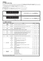
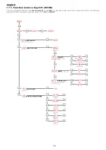
Page 18: ...select the number of program to run SPEE speed Memories running time sec WAIT waiting time Waiting time among memories sec o o o o o enter PALL All programs to 0 1 0240 to PRG4 To program 4 o enter 0 1 0060 enter enter enter enter PRG1 From program 1 enter enter enter enter enter SL slave function Slave unit SL IR SA Stand alone unit IR MA Master unit IRG1 Slave unit group 1 IRG2 Slave unit group ...

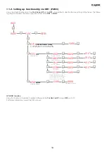
Page 19: ...Test green channel BLU Test blu channel STRB Test strobo STOR T o record the scene of the unit If DMX signal is not applied the recorder setting will appear at the end of reset operation when the unit is switched on menu FUNC MEAS AOO1 MODE o o TESTtest Function test DFSEdefault functions setting To set all the functions at the original values but for DMX address and for working time UPLDUpload So...

Page 20: ...dicates that the user has attempted to set the unit to MASTER mode whilst DMX signal is still being received Detach any DMX control signal or remove MASTER mode settings menu F U NC MEAS AOO1 MODE o o 58C Temperature measurement TEMPtemperature Misure the led housing internal temperature in C enter 10 DMX value reading 255 DMX value reading DMINDMX value on each channel Reading of DMX value 0 255 ...

Page 21: ...ixture Fuse A 2A F 250V Fuse B 4A T 250V 14 2 Periodic maintenance Mechanicals Check that the units is not mechanically damaged Regularly clean the glass by using a soft cloth with a specific cleaning liquid Check the sealing to ensure resistance to water and dust and if necessary replace the damaged parts Electrical components Check all electrical components for correct earthing oxidation and pro...

Page 22: ...If not check the DMX console s output and any cabling for continuity Check the dip switch panel to ensure that no functions are selected which inhibit DMX control Par Lite Led IP may be incorrectly addressed Check the DMX addressing The Par Lite Led IP is set to auto but is not running any programs In addtion to setting the AUTO dip switch to on it is necessary to also select a program number see ...

Page 23: ...46042 Castel Goffredo Mantova Italy ph 39 0376 77521 fax 39 0376 780657 info coemar com Coemar si riserva il diritto di apportare modifiche senza preavviso Coemar reserves the right to effect modifications without notification English ...

Reviews: