background image

35

EC3-680-3 February 2017

Order # 5041558-0 & 5041679-0

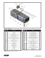
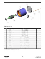
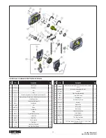
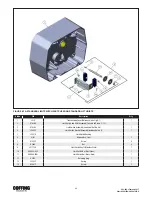
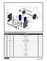
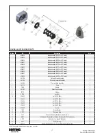
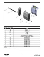
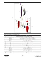
FIGURE 8-8. MOTOR BRAKE PARTS

Ref No

P/N

Description

Qty

854JG24

Brake Assembly (230V, for 2HP Hoists)

854JG20

Brake Assembly (230V, for 3HP Hoists)

854JG25

Brake Assembly (460V, for 2HP Hoists)

854JG21

Brake Assembly (460V, for 3HP Hoists)

854JG26

Brake Assembly (575V, for 2HP Hoists)

854JG22

Brake Assembly (575V, for 3HP Hoists)

854JG27

Brake Assembly (208V, for 2HP Hoists)

854JG23

Brake Assembly (208V, for 3HP Hoists)

854JG37

Brake Assembly (380V, for 2HP Hoists)

854JG36

Brake Assembly (380V, for 3HP Hoists)

2

291JG8

Plate and Frame Assembly

1

3

291JG9

Plate and Armature Assembly

1

4

290JG4

Plate and Stud Assembly

1

5

291J10

Plate

2

6

344J4

Spring

3

7

581JG2

Brake Disc assembly

3

8

JF710

Retainer

1

9

H3978

Lock Nut

3

10

JF853 2

Coil (230V, 60Hz)

1

JF853 3

Coil (460V, 60Hz)

1

JF853 4

Coil (575V, 60Hz)

1

JF853 5

Coil (208V, 60Hz)

1

JF853 6

Coil (380V, 50Hz)

1

11

H2988P

Screw

3

12

142J2

Brake Adapter

1

13

H5527

Retaining Ring

2

14

34J2

Transmission Cover (Reference - See Fig 8-1)

1

15

860J1

Shading Coil Element (Must attache to frame with H7812 adhesive)

2

16

H7812

Adhesive (1 oz. tube) (Not Shown)

1

17

676J1

Decal (Warning)

1

18

200J15

Spacer (Replaces Ref. No. 7 (1) on 2 Hp Brake Assembly Only)

3

NOTE: Standard 230/460 dual voltage units use 230v.

Summary of Contents for EC-10005

Page 1: ...of any hoist presents some risk of personal injury or property damage That risk is greatly increased if proper instructions and warnings are not followed Before using this hoist each operator should become thoroughly familiar with all warnings instructions and recommendations in this manual Retain this manual for future reference and use Forward this manual to the hoist operator Failure to operate...

Page 2: ... piezas de repuesto y centros de servicio situados estratégicamente en Estados Unidos y Canadá Estas instalaciones se han seleccionado en base a su capacidad demostrada en la reparación de equipos y suminstro de piezas de repuesto de forma rápida y eficaz Para obtener la dirección del almacén de piezas de repuesto o del centro de servicio más cercano llame al teléfono 800 888 0985 Fax 716 689 5644...

Page 3: ... potentially hazardous situation THE OPERATOR SHALL a Maintain firm footing or be otherwise secured when operating the hoist b Check brake function by tensioning the hoist prior to each lift operation c Use hook latches Latches are to retain slings chains etc under slack conditions only d Make sure the hook latches are closed and not supporting any parts of the load e Make sure the load is free to...

Page 4: ...weight of your loads Then match them The application the size and type of load the attachments to be used and the period of use must also be taken into consideration in selecting the right hoist for the job Remember the hoist was designed to ease our burden and carelessness not only endangers the operator but in many cases a valuable load DO NOT OPERATE DAMAGED OR MALFUNCTIONING HOIST DO NOT OPERA...

Page 5: ...ling the Load 10 Overload Limiting Protection 10 INSPECTION General 10 Frequent Inspection 10 Periodic Inspection 12 Load Brake Function Check 12 Chain Inspection 13 MAINTENANCE AND REPAIR General 13 Limit Switch Adjustment 13 Motor Break Adjustment 14 Top Suspension Removal and Replacement 14 Chain Replacement 15 Lubrication 16 Chain Stop Installation 18 TROUBLESHOOTING General 18 WIRING Voltage ...

Page 6: ...ure to ambient temperatures below 40 F or above 130 F b Lifting of Hazardous Loads This hoist is not recommended for use in lifting or transporting hazardous loads or materials which could cause Wide spread damage if dropped The lifting of loads which could explode or create chemical or radioactive contamination if dropped requires fail safe redundant supporting devices which are not incorporated ...

Page 7: ...ook block stops at least 2 inches from the bottom of the hoist Run the hoist down to its lower limit At least 12 links of chain should remain on the slack end If either switch is not correct adjust according to the procedure outlined in paragraph 5 2 NOTE The upper and lower limit switches are factory set to provide the maximum allowable hook travel This travel adjustment should not be increased H...

Page 8: ...P 8 Axle 102K11 102K11 9 Retaining Ring H5549 H5549 10 Bearing JF504 2 JF504 2 11 Retaining Ring 5K2658 6W 5K2658 6W 12 Nut Axle H 3945 H 3946 13 Washer H 4211 H 4212 FIGURE 2 1 COFFING CT TROLLEY TABLE 2 2 TROLLEY I BEAM ADJUSTMENT DATA I Beam Size 6 8 10 12 15 18 1 2 and 3 Ton Washers Between Hoist Trolley Thick 0 3 1 4 7 6 Thin 1 0 8 5 3 8 Washers Outside Trolley Thick 7 4 6 3 0 1 Thin 8 9 1 4 ...

Page 9: ...serious damage to hoist may result and hazardous conditions may be created Ass y No DIM A Max Hoist Lift Feet Single Chain Double Chain Triple Chain 927JG201 16 15 927JG202 20 30 15 10 927JG203 24 50 25 16 1 2 927JG204 35 75 37 1 2 25 927JG205 48 3 4 100 50 33 Ass y No DIM A Max Hoist Lift Feet Single Chain Double Chain Triple Chain 927JG207 28 150 75 50 927JG208 35 200 100 66 ...

Page 10: ...l seated before proceeding to lift the load On multiple reeved hoists be sure that the load is equalized on all supporting chains e Lift the load just clear of its supports and stop the hoist to check for proper brake operation f Avoid letting the hook or load swing excessively while moving a trolley suspended hoist 3 4 OVERLOAD LIMITING PROTECTION This hoist is equipped with a factory calibrated ...

Page 11: ...ngs Chain Guides Excessive wear corrosion cracks distortion Nuts Bolts Rivets Looseness stripped and damaged threads corrosion Sheaves Distortion cracks and excessive wear Buildup of foreign substances Housing Load Block Distortion cracks and excessive wear internal buildup of foreign substances Wiring and Terminals Fraying defective insulation Contact Block Magnetic Hoist Control Switch Other Ele...

Page 12: ...r See CHAIN INSPECTION paragraph 4 5 h Inspect hooks and suspension pans for cracks distortion or extreme wear i Inspect hooks for cracks using magnetic particle dye penetrant or other crack detecting methods j Check limit switch set points and reset if necessary see paragraph 5 2 k Inspect all wiring for defective insulation and check to be sure all electrical connections are tight Check motor re...

Page 13: ...is accurately calibrated to operate over the load sprocket and is very carefully heat treated for maximum wear life and strength 1 Do not weld or join hoist load chain 2 Do not substitute another manufacturer s chain in this hoist 3 Damage or wear beyond the stated limits to any portion of the chain requires that the entire length be replaced 4 6 HOOK THROAT OPENING Use Table 4 1 below to check ho...

Page 14: ...ed the multiple disc motor brake should release promptly operate without noticeable chatter and stop the load with no more than one inch of drift If the hoist hesitates to lift the load promptly when the pushbutton is depressed the brake should be adjusted per the following procedure FIGURE 5 2 MOTOR BRAKE ADJUSTMENT a Remove any load and DISCONNECT POWER from hoist b Remove the short end cover c ...

Page 15: ...pply Be sure the green ground wire is properly grounded h Carefully jog the UP button and run the joined pieces of chain into the hoist until about 12 inches of the new chain comes out the other side i DISCONNECT POWER from the hoist All standard top suspensions will be marked with a letter Hoist center sections have each tapped mounting hole marked by a cast in number In order to obtain proper al...

Page 16: ... pipe plug from the side of the hoist With the hoist hanging level transmission oil should be even with the edge of the tapped plug hole d The length of time between necessary oil changes will depend on the severity of use the hoist receives In general the oil should be changed every 12 months of normal operation or every 200 hours of actual hoist on time Very heavy use or operation in high ambien...

Page 17: ...17 EC3 680 3 February 2017 Order 5041558 0 5041679 0 FIGURE 5 5 CHAINING DIAGRAMS ...

Page 18: ...ragraph 5 3 5 Faulty magnetic hoist control switch 5 Check coils for open or short circuit Check all connections in control circuit Check for burned contacts Replace as needed Hook Does Not Stop Promptly 1 Hoist overloaded 1 Reduce load to within rated capacity of hoist 2 Brake not holding 2 Check motor brake adjustment see paragraph 5 3 and load brake Figure 4 3 Hook Moves in Wrong Direction 1 Th...

Page 19: ... with hoist starting Voltage should be no less than 90 of the voltage specified Motor Brake Buzz Anytime hoist is running 1 Brake needs adjustment 1 Adjust as per paragraph 5 3 2 Broken shading coil on brake frame 2 Replace shading coil or complete brake frame assembly SECTION VII WIRING SAFETY NOTES Disconnect power from hoist before removing end covers 7 1 VOLTAGE CONVERSION Standard single spee...

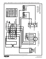
Page 20: ... H4 X1 SEE XFMR CHART PB STATION C20 X1 C21 UP DOWN UP LIMIT SWITCH GOLD NUT TO POWER SUPPLY X2 GND MOTOR 230 460V T1 T2 T3 T4 T5 T6 T7 T8 T9 BRAKE SOLENOID 230V COIL S1 S2 TERMINAL BLOCKS 8 7 6 5 4 3 2 1 T4 T8 T9 H2 H4 C6 C5 C4 C3 T7 T5 T6 S1 S2 8 7 6 5 4 3 2 1 T8 T9 H4 H2 C6 C5 S1 C4 S2 C3 T7 T4 T6 T5 IMPORTANT DUAL VOLTAGE HOIST THREE PHASE HOISTS ARE FACTORY WIRED FOR 460V TO CONVERT VOLTAGE R...

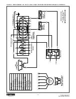
Page 21: ...NOID LINE VOLTAGE S1 S2 C20 C15 C21 DOWN LIMIT SWITCH SILVER NUT C14 UP LIMIT SWITCH GOLD NUT HOIST REVERSING CONTACTOR L3 C14 C15 T1 T2 T3 S1 S2 1 3 5 2 4 6 1 3 5 2 4 6 UP DN A1 A2 A1 A2 X2 H4 H1 L1 L2 TO POWER SUPPLY GND MOTOR 3 PHASE T1 T2 T3 T4 T5 T6 T7 T8 T9 208V AND 575V MOTORS HAVE 3 LEADS 380V MOTORS HAVE 9 LEADS WIRING DIAGRAM 208V 380V 575V 1 SPEED HOIST DWG 98 LE2100 000 380V ONLY Facto...

Page 22: ...460V INSULATE UNUSED H2 OR H4 WIRE X1 COM BLUE X2 24V YELLOW 115V PINK X2 C20 C14 UP LIMIT SWITCH GOLD NUT DOWN C20 C21 X1 7 PB STATION UP T1 T2 T3 T11 T12 T13 2 SPEED MOTOR 3 PH 2 R2 R4 1 R1 R3 FAST 4 3 A2 A1 J2 J1 T12 T11 7 T2 T1 SPEED CONTROL RELAY C14 C15 T13 S1 S2 J1 J2 T3 1 3 5 2 4 6 1 3 5 2 4 6 UP DN A1 A2 A1 A2 L2 L1 L3 H1 HOIST REVERSING CONTACTOR TO POWER SUPPLY SEE XFMR CHART H2 OR H4 X...

Page 23: ...asteners insulators etc These items may be damaged or lost during disassembly or just unfit for future use because of deterioration from age or service Parts should be ordered from COFFING s authorized Master Parts Depots conveniently located throughout the United States and Canada To quickly obtain the name of the Master Parts Depot or Service Center located nearest you call 800 888 0985 Fax 716 ...

Page 24: ...asher 1 12 677J2 Decal Coffing 1 13 H 2987 P Screw 6 14 560J6 Gasket Transmission Cover 1 Ref No P N Description Qty 15 676J2B Decal Coffing Hoists 1 16 679J3 Decal Power Requirements 230 460V 1 16 679J3 Decal Power Requirements 230V 1 16 679J4 Decal Power Requirements 460V 1 16 679J5 Decal Power Requirements 575V 1 16 679J6 Decal Power Requirements 208V 1 16 679J87 Decal Power Requirements 380V 3...

Page 25: ... Mounted 3 Motorized Trolley Parallel Mounted ONLY 1 2 3 Ton Models 4 14J15 Trolley Lug Assembly 3 5 8 4 Motonzed Trolley Cross Mounted 1 2 3 Ton Models 6 14J18 Lug Suspension 7 For 5 Ton Lug Mounted Hoist ONLY 7 14J28 Rigid Hook Assembly With Latch Cross Mounted 8 14J29 Rigid Hook Assembly With Latch Parallel Mounted Standard 9 Load Bar 4 Ton Standard on 8 Wheel Trolley Cross Mounted 10 Load Bar ...

Page 26: ...208V 3Ph 60Hz 1 863J606B 3 HP Motor 208V 3Ph 60Hz 1 861J601B 1 67 HP Motor 380V 3 50HZ 1 861J602B 2 5 HP Motor 380V 3 50HZ 1 873J401 2 HP Two speed Motor 230V 3Ph 60Hz 1 873J402 3 HP Two speed Motor 230V 3Ph 60Hz 1 873J403 2 HP Two speed Motor 460V 3Ph 60Hz 1 873J404 3 HP Two speed Motor 460V 3Ph 60Hz 1 873J405 2 HP Two speed Motor 575V 3Ph 60Hz 1 873J406 3 HP Two speed Motor 575V 3Ph 60Hz 1 873J4...

Page 27: ...Sec 24V 1 821J431 Pri 230V 460V Sec 115V 1 821J452 Pri 575V Sec 24V 1 821J451 Pri 575V Sec 115V 1 821J472 Pri 208V Sec 24V 1 821J471 Pri 208V Sec 115V 1 821J482 Pri 380V Sec 24V 1 821J481 Pri 380V Sec 115V 1 3 H2751 8 3UNC x 5 16 Screw 2 4 H4158 8 External Tooth Lockwasher 2 5 909J10 Terminal Block 230 460V 5 6 909J13 End Clamp 2 7 909J14 Terminal Block 230 460V 3 8 909J15 End Plate 230 460V 2 9 2...

Page 28: ...elay 820J34 24V Coil 1 820J35 115V Coil 1 3 Transformer 821J432 Pri 230V 460V Sec 24V 1 821J431 Pri 230V 460V Sec 115V 1 821J452 Pri 575V Sec 24V 1 821J451 Pri 575V Sec 115V 1 821J472 Pri 208V Sec 24V 1 821J471 Pri 208V Sec 115V 1 821J482 Pri 380V Sec 24V 1 821J481 Pri 380V Sec 115V 1 4 H2751 8 32UNC x 5 16 Screw 2 5 H4158 8 External Tooth Lockwasher 2 6 909J13 End Clamp 2 7 257JG202 Panel Plate 1...

Page 29: ...sion Cover Gasket Reference See figure 8 1 1 30 H5387 Dowel Pin 4 31 35J3 Transmission Housing Reference See figure 8 1 1 32 34J2 Transmission Cover Reference See figure 8 1 1 33 37J6 Sheave Housing Transmission Side Reference See figure 8 1 1 34 402J6 Intermediate Pinion Models EC4024 EC8012 EC10008 1 402J7 Intermediate Pinion Models EC4016 EC8008 EC l0005 1 402J8 Intermediate Pinion Model EC6010...

Page 30: ...X6477 39 O Ring 4 13 H5495P Tail End Pin 1 14 23J5 Spring 1 15 H2219 Socket Head Cap Screw 4 16 H4063P Lockwasher 4 17 H5392 Dowel Pin 2 Ref No P N Description Qty 18 107JG8 7 Drive Coupling 1 20 H6286 Pipe Plug 1 21 19J3 Load Chain Standard AR 21 19J3Z Load Chain Zinc Plated AR 22 913JG2 Bottom Block Assembly Consists of Ref No 23 29 23 30J9 Load Block Frame 2 24 18J7 Pin 1 25 S44 33 Screw 2 26 H...

Page 31: ... 1 20 H6286 Pipe Plug 1 21 19J3 Load Chain Standard AR 21 19J3Z Load Chain Zinc Plated AR Ref No P N Description Qty 22 914JG13 Bottom Block Assembly For 3 Ton Hoist Consists of Ref No 23 30 22 914JG14 Bottom Block Assembly For 4 Ton Hoist Consists of Ref No 23 30 23 3M009A03S Bottom Hook Assembly with latch 1 24 4X1309 Latch Kit 1 25 28JG5 Chain Sprocket assembly 1 26 122JG6 Sheave Pin assembly 1...

Page 32: ...washer 1 17 H5392 Dowel Pin 1 18 107JG8 7 Drive Coupling 1 20 H 6286 Pipe Plug 1 21 19J3 Load Chain Standard AR 21 19J3Z Load Chain Zinc Plated AR Ref No P N Description Qty 22 914JG12 Bottom Block Assembly For 3 Ton Hoist Consists of Ref No 23 31 23 3M009A07S Bottom Hook Assembly with latch 1 24 4X1309 Latch Kit 1 25 28JG6 Chain Sprocket assembly 1 26 30J12 Load Block Frame 2 27 122J7 Sheave pin ...

Page 33: ...embly Consists of Ref no 3 12 3 918JG3 Limit Switch Assembly Consists of Ref No 4 8 1 4 JF900 3 Limit Switch Bracket Assembly includes Ref no 5 1 5 JF531 4 Limit Switch Bushing 6 815J1 Microswitch Limit 2 7 H1402P Screw 4 8 H3944 Nut 4 9 JF117 3S Limit Switch Shaft Stainless Steel 1 10 SK6000 63Z Limit Switch Nut Zinc Silver 1 11 SK6000 63W Limit Switch Nut Brass Gold 1 12 H5520 Retaining Ring 1 1...

Page 34: ... 1 4 PB 287 Spring 1 5 SK6000 63Z Limit Switch Nut Zinc Silver 1 6 SK6000 63W Limit Switch Nut Brass Gold 1 7 117JG2 Shaft and Gear Assembly 1 8 JF531 4 Bushing 1 9 258J8 End Plate 1 10 H4158 Lock Washer 3 11 H2741P Screw 3 12 815J1 Switch 2 13 H3944 Locknut 4 14 427J1 Drive Pinion 1 15 258JG7 Frame and Guide Assembly 1 16 H1402P Screw 4 17 854823 Screw 2 18 H5520 Retaining Ring 1 19 H2981P Mounti...

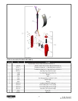
Page 35: ... 3HP Hoists 2 291JG8 Plate and Frame Assembly 1 3 291JG9 Plate and Armature Assembly 1 4 290JG4 Plate and Stud Assembly 1 5 291J10 Plate 2 6 344J4 Spring 3 7 581JG2 Brake Disc assembly 3 8 JF710 Retainer 1 9 H3978 Lock Nut 3 10 JF853 2 Coil 230V 60Hz 1 JF853 3 Coil 460V 60Hz 1 JF853 4 Coil 575V 60Hz 1 JF853 5 Coil 208V 60Hz 1 JF853 6 Coil 380V 50Hz 1 11 H2988P Screw 3 12 142J2 Brake Adapter 1 13 H...

Page 36: ... Fig 8 1 9 Sheave Housing Transmission Side Reference See Fig 8 1 10 12951 Counterweight Kit 40 lbs 11 12952 Counterweight Kit 60 lbs 12 12953 Counterweight Kit 80 lbs 13 12954 Counterweight Kit 100 lbs 14 12955 Counterweight Kit 120 lbs 15 12956 Counterweight Kit 140 lbs 16 12957 Counterweight Kit 160 lbs 17 12958 Counterweight Kit 180 lbs 18 12959 Counterweight Kit 200 lbs 19 12960 Counterweight...

Page 37: ...100 16 Pushbuton Cable Assembly 16 ft Cable Length Consists of Ref No 2 10 PBS2100 Special Drop Equal to the Cable Length 2 36900R Push Button Station Consists Ref No 3 7 9 3 36998R Enclosure 4 36986 Gasket 5 36987 Contact Assembly Consists of Ref No 5 No 6 6 36988 Button Assembly 7 36989 Grommet 8 PBC2100 6 Control Cable Assembly 6 ft Cable Length PBC2100 11 Control Cable Assembly 11 ft Cable Len...

Page 38: ...0 16 Pushbuton Cable Assembly 16 ft Cable Length Consists of Ref No 2 9 PBS2200 Special Drop Equal to the Cable Length 2 36800R Push Button Station Consists Ref No 3 6 3 36998R Enclosure 4 36986 Gasket 5 70964 Contact Assembly Consists of Ref No 5 No 6 6 36988 Button Assembly 7 36866 Grommet 8 PBC2200 6 Control Cable Assembly 6 ft Cable Length PBC2200 11 Control Cable Assembly 11 ft Cable Length P...

Page 39: ...39 EC3 680 3 February 2017 Order 5041558 0 5041679 0 NOTES ...

Page 40: ...40 EC3 680 3 February 2017 Order 5041558 0 5041679 0 NOTES ...

Page 41: ...f the Goods the mechanical components of the Goods will be free from defects in workmanship and materials B IN THE EVENT OF ANY BREACH OF SUCH WARRANTY SELLER S SOLE OBLIGATION SHALL BE EXCLUSIVELY LIMITED TO AT THE OPTION OF SELLER REPAIR OR REPLACEMENT F O B SELLER S POINT OF SHIPMENT OF ANY GOODS THAT SELLER DETERMINES TO HAVE BEEN DEFECTIVE OR IF SELLER DETERMINES THAT SUCH REPAIR OR REPLACEME...

Reviews: