background image

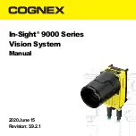
In-Sight

®

9000 Series

Vision System

Manual

2020 June 15
Revision: 5.9.2.1

Summary of Contents for 1AA9

Page 1: ...In Sight 9000 Series Vision System Manual 2020June15 Revision 5 9 2 1...

Page 2: ...t harmful interference when the equipment is operated in a commercial environment This equipment generates uses and can radiate radio frequency energy and if not installed and used in accordance with...

Page 3: ...table is prepared in accordance with the provisions of SJ T 11364 SJ T 11364 O Indicates that said hazardous substance contained in all of the homogeneous materials for this part is below the limit r...

Page 4: ...the pressure on the natural resources we encourage you to use the appropriate take back systems for product disposal Those systems will reuse or recycle most of the materials of the product you are di...

Page 5: ...be followed l Route cables and wires away from high current wiring or high voltage power sources to reduce the risk of damage or malfunction from the following causes over voltage line noise electrost...

Page 6: ...ding can be degraded or cables can be damaged or wear out faster if a service loop or bend radius is tighter than 10X the cable diameter l In Sight 9902L line scan vision system s external LIGHT conne...

Page 7: ...In Sight 9902L 6...

Page 8: ...In Sight 9912 7...

Page 9: ...gnex sales representative Installation procedures and specifications are presented in detail in the In Sight 9000 Series Vision System Reference Guide which is installed with In Sight Explorer softwar...

Page 10: ...back lens is smaller than 19 25mm If the C Mount lens threads and body protrude more than 6 5mm you can add a spacer between the lens and vision system However the spacer decreases the working distan...

Page 11: ...ither by mounting the vision system to a fixture that is electrically grounded or by attaching a wire from the vision system s mounting fixture to frame ground or Earth ground If a ground wire is used...

Page 12: ...ector is not supported 1 Remove the protective cap from the LIGHT connector if present 2 Connect the External Light cable s M12 connector to the vision system s LIGHT connector Note If interference fr...

Page 13: ...Connect the Ethernet cable s RJ 45 connector to a switch router or PC as applicable Connect the Breakout Cable CAUTION To reduce emissions connect the far end of the Breakout cable shield to frame gro...

Page 14: ...power supply and turn it on if necessary Install Software and Documentation To configure an In Sight vision system In Sight Explorer software must be installed on a networked PC In Sight software is a...

Page 15: ...bration test in each of the three main axis for 2 hours 10 Gs 10 to 500 Hz at 100m s 2 15mm with cables or cable plugs and a 150 gram or lighter lens attached 1 To verify case temperature use the EV G...

Page 16: ...d Storage 2 IEC60068 2 6 vibration test in each of the three main axis for 2 hours 10 Gs 10 to 500 Hz at 100m s 2 15mm with cables or cable plugs and a 350 gram or lighter lens attached 1 To verify ca...

Page 17: ...Natick MA 01760 USA In Sight 9902L 1AA9 In Sight 9912 9912C R00064 FCC FCC 15 A FCC 15 A KCC In Sight 9902L 1AA9 R REM CGX 1AA9 In Sight 9912 9912C R00064 R R CGX R00064 NRTL T V S D AM SCC NRTL OSHA...

Page 18: ...RoHS Pb Hg Cd Cr VI PBB PBDE 1AA9 R00064 X O O O O O SJ T 11364 SJ T 11364 O GB T26572 2011 GB T26572 2011 X 1 GB T26572 2011 GB T26572 2011 2...

Page 19: ...2012 7 4 2012 19 EU WEEE 3...

Page 20: ...l UL NRTL 24VDC l 2A l 8A l 100VA LPS Limited Power Source NEC 2 l ESD l l l l 4...

Page 21: ...l 152 4mm 6 10 l In Sight 9902L LIGHT l l l 5...

Page 22: ...In Sight 9902L 6...

Page 23: ...In Sight 9912 7...

Page 24: ...In Sight Explorer In Sight 9000 8...

Page 25: ...C COV 7000 CMNT LG C IP67 C COV 7000 CMNT LG l In Sight 9902L C l 5 25mm l 19 25mm C 6 5mm C 6 5mm l COV 7000 CMNT LG 77mm 55mm 55mm 1 2 3 4 0 90 N m 9...

Page 26: ...4 5 C COV 7000 CMNT LGX C 30mm 13 6 13 4 1 1 2 M4 2 5mm 0 90 N m M4 6mm 3 75mm 10...

Page 27: ...9912 LIGHT In Sight 9902L LIGHT 1 LIGHT 2 M12 LIGHT EFT Fair Rite P N 0431176451 3 11...

Page 28: ...1 M12 ENET 2 RJ 45 PC l I O l 24VDC 1 24VDC OFF 2 I O PLC 12...

Page 29: ...3 24VDC GND 24VDC 4 M12 PWR 5 24VDC In Sight In Sight Explorer PC In Sight In Sight cognex com support insight 1 In Sight Explorer 2 In Sight In Sight 13...

Page 30: ...A 1 0 50 C 20 80 C 80 IP67 IP67 Micro SD IEC 60068 2 27 80 Gs 11 MS 800m s 2 18 X Y Z 3 150 2 IEC 60068 2 6 150 10 Gs 100m s 2 15mm 10 500 Hz 3 2 1 EV GetSystemConfig Internal Temperature 3 5 In Sight...

Page 31: ...VDC 750mA 1 0 50 C 20 80 C 80 IP67 IP67 Micro SD IEC 60068 2 27 150 80 Gs 11 MS 800m s 2 18 X Y Z 3 2 IEC 60068 2 6 350 10 Gs 100m s 2 15mm 10 500 Hz 3 2 1 EV GetSystemConfig Internal Temperature 3 5...

Page 32: ...Regulatory Model 1AA9 In Sight 9912 9912C Regulatory Model R00064 FCC FCC 15 A FCC 15 A KCC In Sight 9902L Regulatory Model 1AA9 R REM CGX 1AA9 In Sight 9912 9912C Regulatory Model R00064 R R CGX R000...

Page 33: ...ble is prepared in accordance with the provisions of SJ T 11364 SJ T 11364 O Indicates that said hazardous substance contained in all of the homogeneous materials for this part is below the limit requ...

Page 34: ...Cognex 2012 7 4 WEEE 2012 19 EU 3...

Page 35: ...Cognex l UL NRTL 24VDC l 2A l 8A l 100VA LPS NEC 2 l ESD l Cognex l l l l 6 10 4...

Page 36: ...l In Sight 9902L LIGHT l l l 5...

Page 37: ...In Sight 9902L 6...

Page 38: ...In Sight 9912 7...

Page 39: ...Cognex In Sight 9000 In Sight Explorer 8...

Page 40: ...T LG C Mount C Mount COV 7000 CMNT LG IP67 l In Sight 9902L C Mount l 5 25mm l 19 25mm C Mount 6 5mm C Mount 6 5mm l COV 7000 CMNT LG 77mm 55mm 55mm 1 2 3 4 0 90 Nm 8 in oz 4 5 C Mount COV 7000 CMNT L...

Page 41: ...6 13 1 2 M4 2 5mm 0 90 Nm 8 in lb M4 6mm 3 75mm 10...

Page 42: ...9912 LIGHT In Sight 9902L LIGHT 1 LIGHT 2 M12 LIGHT EFT Fair Rite 0431176451 3 11...

Page 43: ...1 M12 ENET 2 RJ 45 PC l I O l 24VDC 1 24VDC 2 I O PLC 3 24VDC GND 24VDC 4 M12 PWR 5 24VDC 12...

Page 44: ...In Sight In Sight PC In Sight In Sight cognex com support insight 1 In Sight 2 In Sight In Sight 13...

Page 45: ...2 F 122 F 20 C 80 C 4 F 176 F 80 IP67 IP67 Micro SD IEC 60068 2 27 18 X Y Z 3 80 Gs 800 m s 2 11 ms 150 2 IEC 60068 2 6 2 10 Gs 10 500 Hz 100m s 2 15mm 150 1 EV GetSystemConfig Internal Temperature 3...

Page 46: ...1 0 50 32 F 122 F 20 C 80 C 4 F 176 F 80 IP67 IP67 Micro SD IEC60068 2 27 18 X Y Z 3 80 Gs 800 m s 2 11 ms 350 2 IEC60068 2 6 2 10 Gs 10 500 Hz 100m s 2 15mm 350 1 EV GetSystemConfig Internal Tempera...

Page 47: ...760 USA In Sight 9902L 1AA9 In Sight 9912 9912C R00064 FCC FCC Part 15 Class A FCC Part 15 Class A KCC In Sight 9902L 1AA9 R REM CGX 1AA9 In Sight 9912 9912C R00064 R R CGX R00064 NRTL T V S D AM SCC...

Page 48: ...RoHS Pb Hg Cd 6 Cr VI PBB PBDE 1AA9 R00064 X O O O O O SJ T 11364 SJ T 11364 O GB T26572 2011 GB T26572 2011 X GB T26572 2011 GB T26572 2011 2...

Page 49: ...Cognex WEEE EC 2012 7 4 2012 19 EU x 3...

Page 50: ...Cognex l 24VDC UL NRTL l 2A l 8A l 100VA LPS NEC Class 2 l ESD l Cognex l l l 4...

Page 51: ...l 6 10 l In Sight 9902L l l l 5...

Page 52: ...In Sight 9902L 6...

Page 53: ...In Sight 9912 7...

Page 54: ...Cognex In Sight Explorer In Sight 9000 8...

Page 55: ...C Mount COV 7000 CMNT LG C Mount C Mount COV 7000 CMNT LG IP67 l In Sight 9902L C Mount l 5 25mm l 19 25mm C Mount 6 5mm C Mount 6 5mm l COV 7000 CMNT LG 77mm 55mm 55mm 1 2 3 0 90Nm 8in lb 4 9...

Page 56: ...5 C Mount COV 7000 CMNT LGX C Mount 30mm 13 6 13 4 1 2 M4 2 5mm 0 90Nm 8in lb M4 6mm 3 75mm 10...

Page 57: ...9912 In Sight 9902L 1 2 M12 LIGHT EFT Electrical Fast Transient Fair Rite 0431176451 3 11...

Page 58: ...1 M12 ENET 2 RJ 45 PC l I O l 24VDC 1 24VDC 12...

Page 59: ...2 I O PLC 3 24V DC GND 24V DC 4 M12 PWR 5 24V DC In Sight PC In Sight Explorer In Sight In Sight cognex com support insight 1 In Sight Explorer 2 In Sight Sensor In Sight 13...

Page 60: ...0 C 32 F 122 F 20 C 80 4 F 176 F 80 IP67 IP67 Micro SD IEC 60068 2 27 150g 18 X Y Z 3 80Gs 11ms 800m s 2 2 IEC 60068 2 6 150g 10G 2 100m s 2 15mm 10 500Hz 1 EV GetSystemConfig Internal Temperature 3 5...

Page 61: ...DC 1 0 C 50 C 32 F 122 F 20 C 80 4 F 176 F 80 IP67 IP67 Micro SD IEC60068 2 27 350g 18 X Y Z 3 80Gs 11ms 800m s 2 2 IEC60068 2 6 350g 10G 2 100m s 2 15mm 10 500Hz 1 EV GetSystemConfig Internal Tempera...

Page 62: ...fournir une protection raisonnable contre les parasites en cas d utilisation en environnement commercial Cet quipement g n re utilise et peut diffuser une nergie fr quence radio et s il n est pas inst...

Page 63: ...pr par conform ment aux prescriptions de la norme SJ T 11364 SJ T 11364 O Indique que ladite substance dangereuse contenue dans l ensemble des mat riaux homog nes de cette pi ce est inf rieure au seu...

Page 64: ...et de diminuer l exploitation des ressources naturelles nous vous encourageons utiliser des syst mes de r cup ration adapt s pour l limination du produit Ces syst mes r utilisent ou recyclent proprem...

Page 65: ...de toute autre tension entra ne un risque d incendie ou de d charge lectrique et peut endommager les composants Observez les normes et codes locaux et nationaux en vigueur l Disposez les c bles et les...

Page 66: ...ccord s l utilisateur l Int grez des boucles de service dans les connexions de c bles l Assurez vous que le rayon de courbure des c bles commence au moins six 6 pouces du connecteur Le blindage des c...

Page 67: ...In Sight 9902L 6...

Page 68: ...In Sight 9912 7...

Page 69: ...nt commercial Cognex Les proc dures d installation et les sp cifications sont pr sent es en d tail dans le Guide de r f rence du Syst me de vision InSight s rie 9000 install avec le logiciel InSight E...

Page 70: ...ser de plus de 6 5 mm dans le syst me de vision moins que le diam tre de la lentille post rieure ne soit inf rieur 19 25 mm Si les filets de la monture C et le corps de l objectif d passent de plus de...

Page 71: ...re objectif syst me de vision Faites tourner le couvre objectif dans le sens horaire d environ treize degr s pour le bloquer Montage du Syst me de vision Le syst me de vision pr sente des trous de fix...

Page 72: ...hexagonale de 2 5 mm le couple de serrage maximum est 0 90 Nm 8 in lb Remarque La profondeur maximale d insertion des vis M4 doit tre de 6 mm dans le capot arri re et de 3 75 mm dans le capot avant p...

Page 73: ...In Sight 9902L n est pas pris en charge 1 Retirez le capuchon d objectif recouvrant le connecteur LIGHT s il y a lieu 2 Ins rez le connecteur M12 du c ble d clairage externe dans le connecteur LIGHT d...

Page 74: ...teur ENET du syst me de vision 2 Branchez le connecteur RJ 45 du c ble Ethernet sur un commutateur routeur ou sur le PC selon le cas Connexion du c ble breakout Attention Pour r duire les missions rac...

Page 75: ...5 Remettez le bloc d alimentation 24 VCC sous tension et allumez le si n cessaire Installation du logiciel et de la documentation La configuration du syst me de vision In Sight n cessite l installatio...

Page 76: ...100 m s 2 15 mm avec c bles ou fiches de c ble et un objectif de 150 grammes au maximum en place 1 Pour v rifier la temp rature du bo tier utiliser la commande du mode natif tendu EV GetSystemConfig I...

Page 77: ...pendant 2 heures 10 G 10 500 Hz 100 m s 2 15 mm avec c bles ou fiches de c ble et un objectif de 350 grammes au maximum en place 1 Pour v rifier la temp rature du bo tier utiliser la commande du mode...

Page 78: ...rungen gegeben ist wenn die Ausr stung in einer gewerblichen Umgebung eingesetzt wird Dieses Ger t erzeugt und nutzt Hochfrequenzenergie und kann diese ausstrahlen Wird es nicht entsprechend den Anwe...

Page 79: ...em den Bestimmungen von SJ T 11364 angefertigt SJ T 11364 O Zeigt an dass die Menge der genannten gef hrlichen Substanz in allen homogenisierten Materialien f r dieses Teil unter dem erforderlichen Gr...

Page 80: ...gung des Produkts der jeweils angebotenen R cknahmesysteme zu bedienen Bei diesen Systemen wird der gr te Teil der Materialien des zu entsorgenden Produkts ordnungsgem wiederverwendet oder wiederverwe...

Page 81: ...Stromschlag verursachen und Komponenten besch digen Geltende regionale und nationale Standards und Regelungen f r Verdrahtung Verkabelung m ssen eingehalten werden l Verlegen Sie bitte alle Leitungen...

Page 82: ...n Betrieb des Ger ts entzogen werden l Kabelreserven bei Kabelanschl ssen mit einschlie en l Der Kabel Biegeradius muss mindestens 15cm vom Anschluss entfernt sein Die Kabelschirmung kann sich verschl...

Page 83: ...In Sight 9902L 6...

Page 84: ...In Sight 9912 7...

Page 85: ...ten Sie von einem Cognex Vertriebsmitarbeiter Ausf hrliche Installationsanweisungen und technische Daten finden Sie im Handbuch f r In Sight 9000 Vision Systeme das gemeinsam mit dem Programm In Sight...

Page 86: ...das Objektiv selbst nicht mehr als 6 5mm in der L ngsachse in das Vision System hineinragen wenn sie eingeschraubt sind Wenn das Gewinde des C Mount Objektivs und das Objektiv selbst mehr als 6 5mm in...

Page 87: ...Abdeckung am Vision System Drehen Sie die Abdeckung etwa 13 Grad in Richtung Uhrzeigersinn zur Arretierung Installieren des Vision Systems Das Vision System verf gt ber Befestigungsbohrungen zur Mont...

Page 88: ...iehen Sie die Schrauben mit einem 2 5mm Inbusschl ssel fest max Anzugsmoment 0 90 Nm Hinweis Die maximale Schraubtiefe der M4 Schraube sollte 6mm im hinteren Geh use bzw 3 75mm im vorderen Geh use plu...

Page 89: ...ht 9902L Zeilenscan Vision Systems wird nicht unterst tzt 1 Entfernen Sie ggf den Schutzdeckel vom Lampenanschluss LIGHT 2 Verbinden Sie den M12 Stecker des externen Beleuchtungskabels mit dem Vision...

Page 90: ...leisten 1 Verbinden Sie den M12 Stecker des Ethernet Kabels mit dem Vision System ENET Anschluss 2 Verbinden Sie den RJ45 Anschluss des Ethernet Kabels mit dem PC Switch oder Router Anschlie en des Br...

Page 91: ...es Breakout Kabels mit dem Vision System PWR Anschluss 5 Schlie en Sie das 24VDC Netzteil wieder am Stromnetz an und schalten Sie es ggf ein Installation der Software und Dokumentation Zum Konfigurier...

Page 92: ...lang 10 Gs 10 bis 500 Hz bei 100m s 2 15mm mit Kabeln oder Kabelsteckern und einem befestigten Objektiv mit maximal 150 Gramm 1 Die Geh usetemperatur kann mithilfe des Extended Native Mode Befehls EV...

Page 93: ...rei Hauptachsen 2 Stunden lang 10 Gs 10 bis 500 Hz bei 100m s 2 15mm mit Kabeln oder Kabelsteckern und einem befestigten Objektiv mit maximal 350 Gramm 1 Die Geh usetemperatur kann mithilfe des Extend...

Page 94: ...l mites est n dise ados para ofrecer una protecci n razonable contra interferencias perjudiciales cuando el equipo funciona en un entorno comercial Este equipo genera utiliza y puede emitir energ a d...

Page 95: ...a conforme a las disposiciones de SJ T 11364 SJ T 11364 O Indica que la sustancia nociva mencionada anteriormente contenida en todos los materiales homog neos de esta pieza est por debajo del l mite r...

Page 96: ...n sobre los recursos naturales le alentamos a utilizar los sistemas de recogida apropiados para la eliminaci n del producto Estos sistemas reutilizar n o reciclar n la mayor a de los materiales del p...

Page 97: ...plicaci n de cualquier otra tensi n supone un riesgo de incendio o de descarga el ctrica y puede da ar los componentes Deber n cumplirse las normas y los reglamentos sobre cableado tanto locales como...

Page 98: ...zar el equipo l Deje bujes de holgura en todas las conexiones de cable l Aseg rese de que el radio de un tramo de cable curvado empieza al menos a seis pulgadas del conector Si el radio de un tramo de...

Page 99: ...In Sight 9902L 6...

Page 100: ...In Sight 9912 7...

Page 101: ...imientos de instalaci n y las especificaciones se explican detalladamente en la Gu a de referencia de InSight serie 9000 Sistema de visi n que se instala autom ticamente con el software InSight Explor...

Page 102: ...lir m s de 6 5 mm de la longitud del sistema de visi n atornillado a menos que el di metro de la lente trasera tenga menos de 19 25 mm Si las roscas y el cuerpo de la lente de montura C sobresaliesen...

Page 103: ...ierta al sistema de visi n Gire la cubierta hacia la derecha unos trece grados para bloquearla Montaje del Sistema de visi n El sistema de visi n dispone de orificios de montaje para acoplarlo a una s...

Page 104: ...una llave hexagonal de 2 5 mm aplicando un par de apriete m ximo de 0 90 Nm 8 pulg lb Nota La profundidad de inserci n m xima de los tornillos M4 deber a ser de 6 mm en la carcasa trasera y de 3 75 mm...

Page 105: ...de exploraci n por l neas In Sight 9902L 1 Retire la cubierta protectora del conector LIGHT si existe 2 Enchufe el conector M12 del cable de luz externa al conector LIGHT del sistema de visi n Nota Si...

Page 106: ...r M12 del cable Ethernet en el conector ENET del sistema de visi n 2 Enchufe el conector RJ 45 del cable Ethernet a un conmutador enrutador o PC seg n corresponda Conexi n del cable de conexi n Precau...

Page 107: ...nexi n al conector PWR del sistema de visi n 5 Restablezca el suministro el ctrico a la fuente de alimentaci n de 24 V CC y enci ndala si fuese necesario Instalar el software y la documentaci n Para c...

Page 108: ...ante 2 horas a 10 Gs de 10 a 500 Hz a 100 m s 2 15 mm con cables o conectores para cables y una lente de 150 gramos o m s ligera conectada 1 Para verificar la temperatura de la carcasa ejecute el coma...

Page 109: ...s tres ejes principales durante 2 horas a 10 Gs de 10 a 500 Hz a 100 m s 2 15 mm con cables o conectores para cables y una lente de 350 gramos o m s ligera conectada 1 Para verificar la temperatura de...

Page 110: ...Copyright 2018 2020 Cognex Corporation All Rights Reserved...

Reviews: