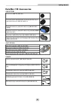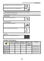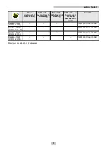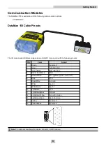
Reader Layout
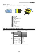
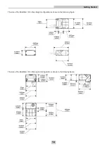
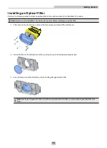
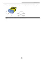
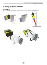
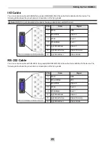
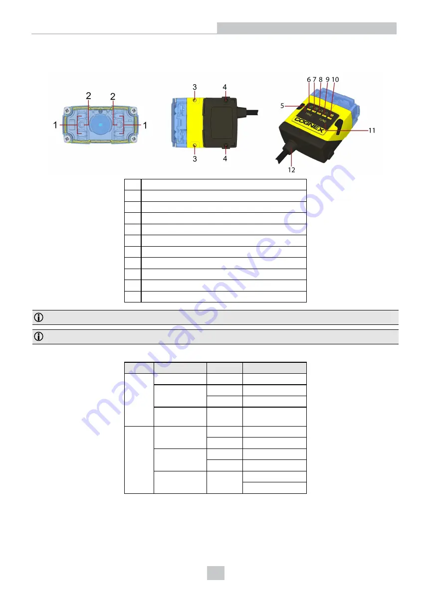
The following images show the built-in lighting system and other features of the DataMan 150 reader.
1
Illumination LEDs
2
LED aimers
3-4* Mounting holes (M3 x 3.5mm)
5
Trigger button
6
Power
7
Train status/Trigger status
8
Good/bad read
9
Communication
10
Error
11
Tune button
12
Power, I/O and RS-232
Note
: *Use only one set of mounting holes (either 3 OR 4) for mounting.
Note
: The five status LEDs together also function as a peak meter using an orange light.
Indicator LEDs
Type
Signal
Color
Meaning
Status
Power
GREEN
Power ON
Train status
GREEN
Trained
YELLOW
Untrained
Error
RED
Error - check
device log
Action
Good/bad read
GREEN
Good read
RED
Bad read
Communication YELLOW
Link up
blink
Data transfer
Peak meter
Yellow
Tune
Focus
10
Getting Started


