background image

Specifications

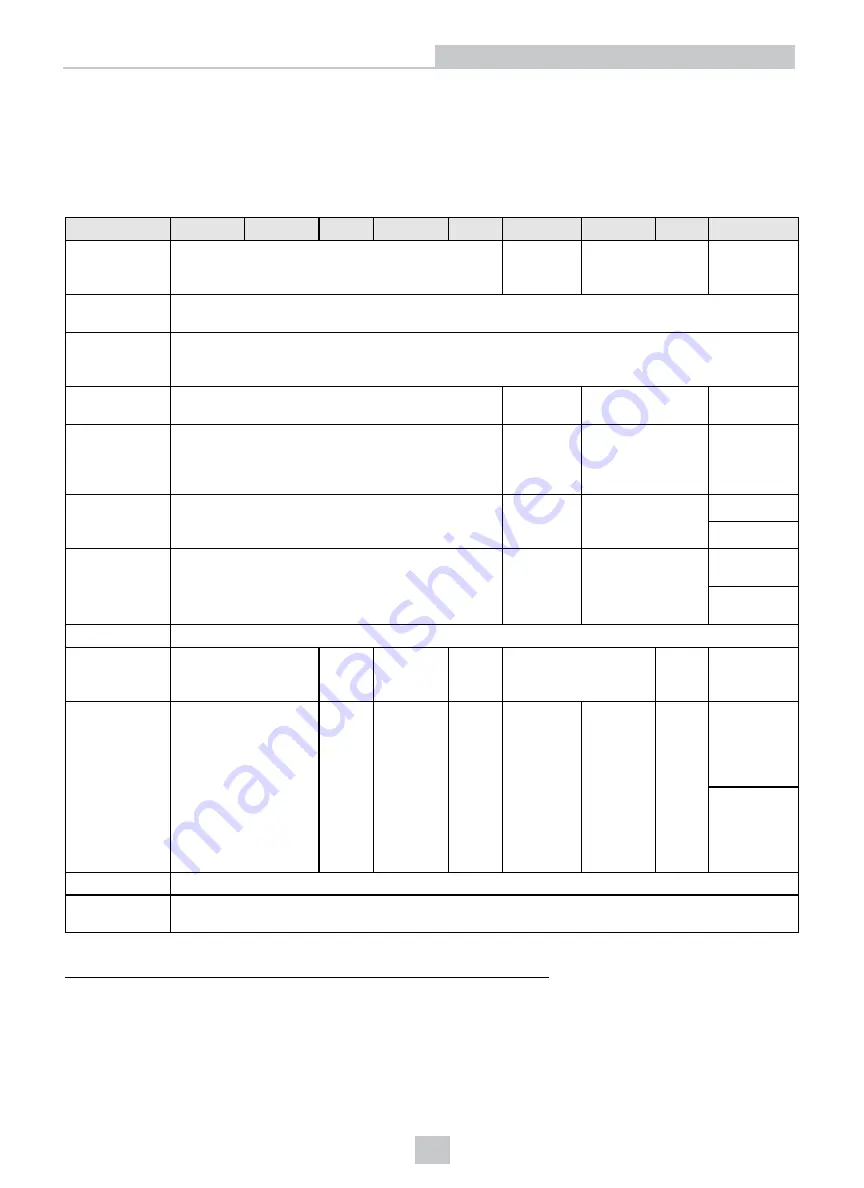
The following sections list general specifications for the In-Sight Micro vision systems.

In-Sight Micro Vision System Specifications

Specifications 1020/1050 1100/1110 1100C 1400/1410 1400C

1402/1412 1403/1413 1403C

1500

Minimum
Firmware
Requirement

In-Sight version 4.4.3

In-Sight
version
4.6.0

In-Sight version
4.4.3

In-Sight
version 4.9.1

Job/Program
Memory

128MB non-volatile flash memory; unlimited storage using a remote network device.

Image
Processing
Memory

256MB SDRAM

Sensor Type

1/3-inch CCD

1/1.8-inch
CMOS

1/1.8-inch CCD

1/1.8-inch
CMOS

Sensor
Properties

5.92mm diagonal, 7.4 x 7.4µm sq. pixels

8.7mm
diagonal,
5.3 x 5.3µm
sq. pixels

8.8mm diagonal,
4.4 x 4.4µm sq.
pixels

8.7mm
diagonal, 5.3
x 5.3µm sq.
pixels

Maximum
Resolution
(pixels)

1

640 x 480

1280 x
1024

1600 x 1200

640 x 480

800 x 600

2

Electronic
Shutter Speed

16µs to 1000ms

16µs to
950ms

52µs to 1000ms

640 x 480:
4µs to 500ms

800 x 600:
5µs to 500ms

Acquisition

Rapid reset, progressive scan, full-frame integration.

Bit Depth

256 grey levels (8
bits/pixel)

24-bit
color

256 grey
levels (8
bits/pixel)

24-bit
color

256 grey levels (8
bits/pixel)

24-bit
color

256 grey
levels (8
bits/pixel)

Frames Per
Second

3

60 full frames per
second

58 full
frames
per
second

60 full
frames per
second

58 full
frames
per
second

60 full
frames per
second

14 full
frames per
second

7 full
frames
per
second

640 x 480
resolution:
213 full
frames per
second

800 x 600
resolution:
157 full
frames per
second

Lens Type

CS-mount and C-mount (with 5mm extension, included).

Trigger

1 opto-isolated, acquisition trigger input. Remote software commands via Ethernet. (RS-232C
available when using the optional CIO-MICRO or CIO-MICRO-CC I/O module.)

1

You can configure the number of image sensor rows and set them in the In-Sight Explorer software. If you decrease the number of rows, it
increases the frames per second acquired by the vision system. Refer to the AcquireImage topic in the

In-Sight

®

Explorer Help

file for more

information.

2

The default resolution for the In-Sight Micro 1500 vision system is 640 x 480 pixels. The vision system's resolution can be configured as 800 x
600 pixels within the In-Sight Explorer software. Refer to the

In-Sight

®

Explorer Help

file for more information.

3

Maximum frames per second are job-dependent, based on the minimum exposure for a full image frame capture using the dedicated
acquisition trigger, and assumes there is no user interface connection to the vision system.

18

Specifications

Summary of Contents for In-Sight Micro Series

Page 1: ...In Sight Micro Series Vision System Installation Manual 2019August24 Revision 5 7 4 3...

Page 2: ...means electronic or mechanical for any purpose nor transferred to any other media or language without the written permission of Cognex Corporation Copyright 2008 2019 Cognex Corporation All Rights Res...

Page 3: ...th the limits for a Class A digital device pursuant to part 15 of the FCC Rules These limits are designed to provide reasonable protection against harmful interference when the equipment is operated i...

Page 4: ...e on the natural resources we encourage you to use the appropriate take back systems for product disposal Those systems will reuse or recycle most of the materials of the product you are disposing in...

Page 5: ...ards such as excessive heat dust moisture humidity impact vibration corrosive substances flammable substances or static electricity l Do not expose the image sensor to laser light Image sensors can be...

Page 6: ...O Module Cable 13 Connect the Ethernet and Power 14 Connect the Power Wires 14 Connect the Frame Ground Wire 15 Connect an RJ 45 LAN Cable 16 Connect the Ethernet Cable 16 Specifications 18 In Sight M...

Page 7: ...lp files provided with In Sight Explorer software l On demand training cognex com on demand training aspx l The In Sight online support site cognex com support insight Standard Components In Sight Mic...

Page 8: ...ted in the Ethernet Cable Specifications on page 24 This cable is available in the lengths and styles listed below Length Standard Part 45 Degree Key Right Angle Part 135 Degree Key Right Angle Part 0...

Page 9: ...05 10 m CCB M8IO 10 15 m CCB M8IO 15 I O Module Cable The I O Module cable is used with the CIO MICRO or CIO MICRO CC I O module The I O Module cable connects the vision system directly to the I O mod...

Page 10: ...m LED1 Green when active User configurable using Discrete Output Line 4 Line 10 when using the CIO MICRO or CIO MICRO CC I O module LED2 Red when active User configurable using Discrete Output Line 5...

Page 11: ...n page 27 1 Align the mounting block with the mounting holes on the vision system 2 Insert the M3x6 quantity 4 screws into the mounting holes and tighten the screws using a 2 5mm hex wrench the maximu...

Page 12: ...n system must be Online for the discrete inputs and outputs to function l Refer to the In Sight Explorer Help file for details on configuring the discrete input and output lines Option 1 Connect the B...

Page 13: ...Connect the I O Module Cable 1 Connect the I O Module cable s M8 connector to the vision system I O connector 2 Connect the I O Module cable s DB15 connector to the I O module s I O connector 13 Inst...

Page 14: ...tion Manual Connect the Power Wires CAUTION Never connect the I O module to a power source other than 24VDC Any other voltage creates a risk of fire or shock and can damage the hardware Do not connect...

Page 15: ...ections of the RS 232 port LAN port PoE port I O port and Frame Ground terminal are internally connected The system grounding is at a zero ground potential This zero ground potential extends through t...

Page 16: ...et Cable CAUTION l All cable connectors are keyed to fit the connectors on the vision system Do not force the connections or damage may occur l The I O module s PoE port provides power and Ethernet co...

Page 17: ...2 Connect the Ethernet cable s RJ 45 connector to the I O module s PoE port 3 Restore power to the 24VDC power supply and turn it on if necessary 17 Installation...

Page 18: ...256 grey levels 8 bits pixel Frames Per Second3 60 full frames per second 58 full frames per second 60 full frames per second 58 full frames per second 60 full frames per second 14 full frames per sec...

Page 19: ...6 49 W maximum per Class 2 PoE Current Per Class 2 PoE requirements Voltage 48VDC nominal applied from a Class 2 PoE injector which is typically powered from some other voltage Material Die cast zinc...

Page 20: ...mum latency between leading edge of trigger and start of acquisition Input pulse should be minimum of 1 ms wide In Sight Micro 1403C 116 s maximum latency between leading edge of trigger and start of...

Page 21: ...and the positive supply voltage 24VDC nominal HS COMMON should be connected to the negative supply voltage 0VDC The outputs pull down to less than 3VDC when ON which causes current to flow through th...

Page 22: ...less than 3VDC For more information refer to the Breakout Cable Specifications on page 25 High Speed Output PNP Configuration The Breakout cable can be used to connect to a PNP compatible PLC input C...

Page 23: ...t and the positive side to 24VDC When the output switches on the negative side of the load is pulled down to less than 3VDC and greater than 21VDC appears across the load Use a protection diode for a...

Page 24: ...ion system P1 Pin Signal Name Wire Color P2 Pin 6 TPO 48VDC Mode A White Orange 1 4 TPO 48VDC Mode A Orange 2 5 TPI 48VDC RTN Mode A White Green 3 7 48VDC Mode B Blue 4 1 48VDC Mode B White Blue 5 8 T...

Page 25: ...ted to devices such as a PLC trigger sensor or strobe light The Breakout cable is not terminated P1 Pin Signal Wire Color 1 HS OUT 0 Brown 2 HS OUT 1 White 3 TRIGGER Blue 4 TRIGGER Black 5 HS COMMON G...

Page 26: ...ia the DB15 connector When connected the I O Module cable provides access to the vision system s trigger and high speed outputs P1 Pin Signal Name P2 Pin 1 HS OUT 0 4 2 HS OUT 1 5 3 TRIGGER 2 4 TRIGGE...

Page 27: ...f the vision system and optional accessories Vision System Dimensions Note l Dimensions are in millimeters inches and are for reference purposes only l All specifications are for reference purposes on...

Page 28: ...Dimensions with Mounting Block Note l Dimensions are in millimeters inches and are for reference purposes only l All specifications are for reference purposes only and can change without notice 28 Sp...
Page 29: ...rrosive solvents including lye methyl ethyl ketone MEK or gasoline Clean the Vision System Image Sensor Window To remove dust from the outside of the image sensor window use a pressurized air duster T...

Page 30: ......

Reviews: