background image

SYMBOL GLOSS 

23 


OM.SS60.20141016 


APPENDIX B:  TRANSFORMER 
CONFIGURATION 

IN THIS SECTION 

High Voltage Connection . . . . . . . . . . . 23 
Normal / Medium Voltage Connection. . . . . . 24 


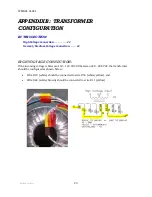
HIGH VOLTAGE CONNECTION: 

If the incoming voltage is between 118 – 140 VAC 

OR

 between 240 – 285 VAC, the transformer 

should be configured as shown below: 


Wire #43 (white) should be connected to wire #55 (white/yellow), and  


Wire #44 (white/brown) should be connected to wire #11 (yellow) 


Summary of Contents for SDI Select 60

Page 1: ...OM SS60 20141016 OPERATOR MANUAL SDI Select 60 OPERATOR MANUAL Original Instructions September 2018 ...

Page 2: ...this document is error free No part of this publication may be reproduced stored in a retrieval system or transmitted in any form or by any means electronic mechanical photocopying recording or otherwise without the prior written permission of Cold Jet This manual reflects the product configuration as was current at the time of initial prototypes An item s display in this catalog does not guarante...

Page 3: ...OM SS60 20141016 ...

Page 4: ...OM SS60 20141016 ...

Page 5: ...ONTACTINGCOLDJET19 APPENDIXA BLASTAIRQUALITY21 Plant Air Central Compressed Air System 21 Using Portable Air 85 500 hp 64 373 kw 22 APPENDIXB TRANSFORMERCONFIGURATION23 High Voltage Connection 23 Normal Medium Voltage Connection 24 SYMBOLGLOSSARY25 Yellow Warning Triangle Black Graphical Symbols 26 Blue Mandatory Action Circle White Graphical Symbols 27 Red Circle With Slash Black Graphical Symbol...

Page 6: ......

Page 7: ...tor Always turn source air OFF and bleed down the system before disconnecting the air supply hose Always turnsource air OFF and remove the applicator control line before removing the blast hose Always follow all of the governing codes of your local national body Always ensure the finger guard over the feeder exhaust port is installed The finger guard on the feeder protects from a potential persona...

Page 8: ...let This step is critical for electrostatic dissipation If the ground is not connected a charge may build up on the unit or the applicator CO2 SAFETY The SDI Select 60 uses solid state carbon dioxide CO2 CO2 is nontoxic non corrosive and nonconductive It is approved by the FDA and USDA Solid CO2 is extremely cold 109 F 78 C Always protect skin from direct contact with CO2 pellets nuggets or slices...

Page 9: ...t empty 334 lbs 161 kg 365 lbs 166 kg with optional pressure regulator Dimensions 28 x 24 x 43 in 72 x 61 x 110 cm Dry Ice Capacity 60 lbs 27 2 kg Dry Ice Block 50 lbs 22 6 kg Dry Ice Pellets Trough Hopper is 12 x 10 x 12 in 300 x 250 x 300 mm Variable Feed Rate 0 6 lbs min 0 2 7 kg min Power Requirements 100 140 VAC 1 50 60 Hz 8 A 200 240 VAC 1 50 60 Hz 4 A Feeder Drive 1 HP 3 Phase AC Variable S...

Page 10: ...SDI SELECT 60 USER MANUAL 4 OM SS60 20141016 FRONT VIEW dry ice pellet nugget loading lid whip check cable dry ice block loading door bleed valve air supply brakes ...

Page 11: ...COMPONENT GUIDE 5 OM SS60 20141016 REAR VIEW dry ice level indicator blast cable connector power cord blast hose connector control panel see p 6 compressed air nozzle nozzle hanger ...

Page 12: ...OL PANEL power switch pusher plate retract switch hour meter regulator bypass switch optional agitation control switch incoming air pressure disable blast button blast pressure control optional dry ice feed rate control regulated air pressure optional ...

Page 13: ... 7 OM SS60 20141016 Symbol Meaning Symbol Meaning agitation control intermittent off on regulator bypass bypass regulated variable dry ice feed rate disable blast pusher plate retract hour meter regulated air pressure ...

Page 14: ...LICATOR NOTE THE BLAST APPLICATOR PICTURED INCLUDES AN OPTIONAL LIGHT air ice air only on off LED light switch optional nozzle retention collar applicator safety switch blast hose connector air ice control trigger blast cable connection LED light optional ...

Page 15: ...ee of debris use compressed air nozzle if it is not To start the SDI Select 60 1 Securely attach the blast hose and control cable to the SDI Select 60 2 Securely attach the blast applicator to the blast hose and control cable 3 Securely attach a nozzle to the blast applicator 4 Securely attach the air supply hose to the SDI Select 60 and fully extend hose whip check 5 Securely attach the static bo...

Page 16: ...p 13 If using ice blocks slices load through the dry ice block loading door placing dry ice against the rotary knives For best performance position smaller blocks slices as shown in the following image when stacking them in the trough If using pellets nuggets load through the dry ice pellet nugget loading lid Fill to the top of the blade wheel Do not overfill the SDI Select 60 fill only to the top...

Page 17: ...icles want to cling together The agitation control switch s right position is MANUAL I The SDI Select 60 will blast air into the feeder chamber and the thumper agitation will actuate as long as the switch is held in this position The manual setting can be used as necessary to ensure the trough and feeder chamber remain free and clear of any buildup that may form during use Cold Jet recommends usin...

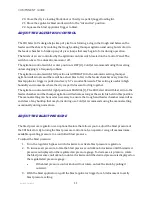
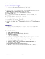
Page 18: ...To find the optimum feed rate set the feeder speed to 0 and increase the rate to achieve desired results SHUT DOWN Always wear gloves to protect hands from exposure to cryogenic temperatures and sharp blade surfaces To shut down the SDI Select 60 1 Release trigger to stop blasting 2 Move the blast applicator mode switch to the Off position 3 Press the disable blast button The button will illuminat...

Page 19: ...temperatures and sharp blade surfaces 1 Insert a flat head screwdriver in the slot at the end of the lever and lift lever 2 Push the slide into the open position for pellet blasting or into the closed position for shaved blasting The dry ice used for pellet blasting must be 3 mm or smaller if the sliding pellet doors are in the open position The following image shows the sliding pellet door in the...

Page 20: ...ECT 60 USER MANUAL 14 OM SS60 20141016 The following image shows the sliding pellet door in the closed position for block slice nugget blasting With a glove protected finger close the lever to secure the slide ...

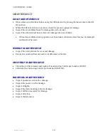
Page 21: ...ring operation or hose leak is otherwise detected hose is damaged and must not be used WEEKLY MAINTENANCE Inspect the rotary knives for wear and damage Ensure the nozzle airflow exit end is not deformed or burred MONTHLY MAINTENANCE Check the air filter element and replace if needed using Cold Jet part number 4I0308 Lubricate the chain using Cold Jet part number 80635 001 BIANNUAL MAINTENANCE Insp...

Page 22: ...ing the applicator trigger turn the agitation control switch to the right I 4 Repeat step 3 until no dry ice comes out of the nozzle If steps 1 through 4 do not work there is a serious clog Proceed to step 5 5 Open dry ice pellet nugget loading lid 6 Open the cleanout access door located at top of shaver wheel assembly Remember to use preventative methods to avoid clogging in extremely humid envir...

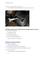
Page 23: ...g the SDI Select 60 in 2 Is there electric at the outlet Turn the power on to the outlet 3 Is the power switch in the ON I position Move power switch to the ON I position SDI SELECT 60 WILL NOT BLAST 1 Is the disable blast light on Pull the disable blast button out 2 Is the applicator blast mode switch in the Off position Move the applicator blast mode switch to the Air and Ice position 3 Is the a...

Page 24: ...y ice been placed behind the pusher plate Remove dry ice push the plate to the back of the trough and re load dry ice 3 Do rotary knives look damaged Call Cold Jet for support 4 Is too much dry ice clogging the feeder chute Complete the Unclog the Dry Ice Chute procedure p 16 17 5 Is the feeder rate greater than 0 Increase feeder rate 6 Is the dry ice loading block door or the dry ice pellet nugge...

Page 25: ...1 1209 After Hours Technical Support 1 800 777 9101 Latin America Cold Jet Latinoamérica Phone 52 81 1097 0445 After Hours Technical Support 1 513 576 8981 Europe Belgium Cold Jet Europe bvba European Headquarters Phone 32 0 13 53 95 47 FAX 32 0 13 53 95 49 After Hours Technical Support 1 513 576 8981 Germany Cold Jet Deutschland GmbH Phone 49 0 6551 9606 0 FAX 49 0 6551 9606 26 After Hours Techni...

Page 26: ......

Page 27: ...me watch the pressure gauge while blasting If the gauge drops slowly the compressor is insufficient If the gauge drops quickly there is a restriction or the pipe is too small If the gauge stays steady then the compressor and piping are adequate To maintain adequate pressure to the SDI Select 60 For distances less than 50 ft 15 m between the air compressor and the SDI Select 60 Cold Jet recommends ...

Page 28: ...n the nozzle causing a jam Ice may exit the nozzle and damage the target surface If blasting continuously use an air dryer to further reduce the air moisture dew point Desiccant dryers produce a dew point of 40 F 40 C resulting in a dew point low enough for continuous blasting To verify the compressor is of adequate size for the SDI Select 60 the air compressor needs to produce an air volume 10 gr...

Page 29: ...ion 23 Normal Medium Voltage Connection 24 HIGH VOLTAGE CONNECTION If the incoming voltage is between 118 140 VAC OR between 240 285 VAC the transformer should be configured as shown below Wire 43 white should be connected to wire 55 white yellow and Wire 44 white brown should be connected to wire 11 yellow ...

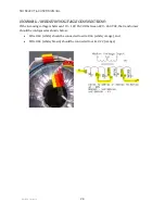
Page 30: ... VOLTAGE CONNECTION If the incoming voltage is between 110 128 VAC OR between 220 260 VAC the transformer should be configured as shown below Wire 43 white should be connected to wire 66 white orange and Wire 44 white brown should be connected to wire 22 orange ...

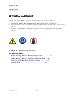
Page 31: ...mandatory action circle white graphical symbol indicates an action to take to avoid the hazard 3 A red circle with slash black graphical symbol indicates a prohibited action to avoid the hazard All symbols may not apply to the SDI Select 60 IN THIS SECTION Yellow Warning Triangle Black Graphical Symbols 26 Blue Mandatory Action Circle White Graphical Symbols 27 Red Circle With Slash Black Graphica...

Page 32: ...ning Symbol Meaning burn hazard hot surface hand crush force from top and bottom electrical shock electrocution hand crush moving parts general danger hand entanglement belt drive top hand crush force from above hand entanglement belt drive hand crush force from below hand entanglement chain drive hand crush force from left lifting hazard hand crush force from right low temperature ...

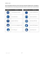
Page 33: ...le white graphical symbol indicates an action to take to avoid the hazard Symbol Meaning Symbol Meaning consult operators manual maintain safe pressure disconnect power wear ear protection general mandatory wear eye protection lock out in de energized state wear protective gloves lock out tag out wear safety boots ...

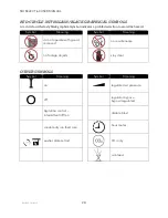
Page 34: ...n to avoid the hazard Symbol Meaning Symbol Meaning do not operate with guard removed no maintenance no foreign objects stay clear OTHER SYMBOLS Symbol Meaning Symbol Meaning on regulated air pressure off regulator bypass bypass regulated Agitation control intermittent off on disable blast variable dry ice feed rate hour meter pusher plate retract CO2 only air bleed ...

Page 35: ...l as warranted CJ may replace the Equipment in its entirety at its discretion Any claim must be made in writing to CJ within 30 days after the defect is discovered and any claim not made within that period shall be deemed waived or released and denied Warranty service provided under this Agreement does not assume uninterrupted operation of the Equipment The suitability of the equipment for the pur...

Page 36: ...SDI SELECT 60 USER MANUAL ...

Page 37: ...31 OM SS60 20141016 SECTION 7 SCHEMATICS IN THIS SECTION Basic Mechanical Schematic Pneumatic Schematic Electrical Schematic ...

Page 38: ...SDI SELECT 60 USER MANUAL ...

Page 39: ...t 19 Control Panel 6 Daily Maintenance 15 Electrostatic Discharge 2 General Safety Requirements 1 Ground the Material Being Cleaned 2 Maintenance 15 Monthly Maintenance 15 Plant Air 21 PORTABLE AIR 22 red circle with slash black graphical symbol 25 28 Safety Guidelines 1 Shut Down 12 Specifications 3 Start Up 9 Symbol Glossary 25 Troubleshooting 16 Unclog the Dry Ice Chute 16 18 Unit Operation 9 W...

Page 40: ...SDI SELECT 60 USER MANUAL ...

Page 41: ...TRAINING VIDEO ...

Page 42: ...SDI SELECT 60 USER MANUAL ...

Reviews: