MNL_Standard-NoSpecs_ACWC-18to240-E-_(0713).docx
- 10 -
clear sight glass for optimum performance. Returning fluid temperature should not exceed 90°F on
standard units or the chiller will cycle off on high head pressure and not run. Should this occur, allow
water to cool down and restarting chiller once water is below 90°F.
e)
If sight glass is bubbly add to charge. If clear, reduce the charge to bubbles and clear. Allow five (5)
minutes run time for equalization.
f)
Re-check superheat and adjust as required.
V.
SYSTEM COMPONENTS: (See your chiller’s specification for details.)
1.
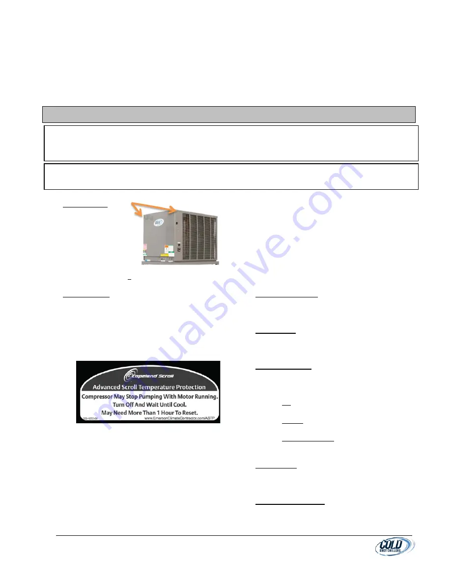
ACCESS PANEL
a.
Viewed facing
front panel
(where the
Cold Shot
Chillers logo is
located).
b.
Panels on
larger systems (>120kBtu/hr) must have all
panels installed when operating.
2.
COMPRESSORS
a.
Scroll compressors are hermetically sealed
with internal motor overload protection.
b.
Most Copeland compressors are equipped
with an advanced scroll temperature
protection (ASTP). A label located above the
terminal box identifies models that contain
this technology.
c.
Advanced scroll temperature protection is a
form of internal discharge temperature
protection that unloads the scroll compressor
when the internal temperature reaches
approximately 300 F. At this temperature, an
internal bi-metal disk valve opens and causes
the scroll elements to separate, which stops
compression. Suction and discharge pressures
balance while the motor continues to run. The
longer the compressor runs unloaded, the
longer it must cool before the bi-metal disk
resets. Eventually, the motor’s internal
thermal electrical protection will shut down
the compressor.
d.
To manually reset ASTP, the compressor
should be stopped and allowed to cool. If the
compressor is not stopped, the motor will run
until the motor protector trips, which occurs
up to 90 minutes later. Advanced scroll
temperature protection will reset
automatically before the motor protector
resets, which may take up to 2 hours.
3.
CRANKCASE HEATER
a.
This minimizes absorption of liquid refrigerant
by oil in casing during brief or extended
shutdown periods.
4.
CONTROLLER
a.
The digital temperature controller may vary in
design. For controller details, see the
Controller Section of this manual.
5.
CONDENSER FANS
a.
Fans operate along with the compressor
operation along with the mode controls.
b.
Modes of fan cycling are:
a)
On (whenever the compressor is on).
(Typically, 3ton and under)
b)
Cycling (with use of pressure actuated
“head pressure switch”. (5ton and over)
c)
Speed Controlled (if using a low ambient
fan speed controller device when
operating in low ambient condition).
6.
FILTER/DRIER
a.
For system cleanliness and moisture capture.
Every unit will have a filter drier factory
installed.
7.
MOISTURE INDICATOR
a.
For system charging and moisture condition.
Every unit will have a sight glass (moisture
indicator) factory installed.
IMPORTANT
: Never open any switch or disconnect that de-energizes the crankcase heater unless unit is being
serviced or is to be shut down for a prolonged period. After a prolonged shutdown on a service job, energize
the crankcase heater for 24 hours before starting the compressor.
NOTE
: Schrader valve cores: Most components connected to a refrigerant fitting include a Schrader valve for
servicing. If leakage occurs during removal of a component, the valve may have been removed or damaged.


