Marrone & Co., Inc.
2730 Maximilian Drive • Houston, Texas 77032 • Phone (281) 227-8400 • (800) 473-9178
Fax (281) 227-8404 • www.waterchillers.com
Guide_DeltaPLC-ProgramOperations-A1_020816.docx
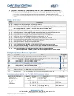
IMPORTANT! Continuous restarting of the system with a fault is considered abuse and will void all warranties.
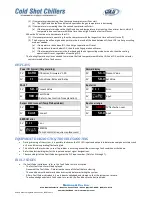
The Temperature Controller has additional normally open contacts available that will close during an alarm situation.
-
Alarm Output 1 indicates that the Process temperature has exceeded the allowable temperature range limits.
-
Alarm Output 2 indicates that the Process temperature has exceeded the allowable temperature limits.
-
Alarm Output 3 indicates that the Process temperature has deviated from the set value by the deviation high or low
values.
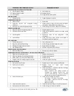
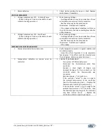
FAULT CODE LIST
FAULT
CODE
DESCRIPTION
9 0 0 0
Only shown if there are no settings in the DTB Temperature Controller
9 1 0 0
Set Value Temperature Outside the Permitted Range (Will reset the nearest range temperature limit)
9 1 1 0
Process Value has Deviated Higher Than Set Value Limit without lowering within time period (approx 30 minutes). If this occurs
and the cause is known, then raise the SV to be closer to the PV to permit recirculating system.
9 1 2 0
Process Value Temperature Too High
9 2 0 0
Refrigerant Pressure Too High at Startup (High Pressure Switch is open) – If manual switch, then press reset.
9 2 1 0
Refrigerant Pressure Too High during Operation (High Pressure Switch is open) – If manual switch, then press reset.
9 3 0 0
Refrigerant Pressure Low at Startup or During Pump Operation (Low Pressure Switch is open)
9 3 1 0
Refrigerant Pressure Low during Compressor Operation after Initial Compressor Start Bypass Timer
9 4 0 0
No Fluid Flow. Flow was not established in the initial time period (typically 5 seconds)
9 4 1 0
Fluid Flow Loss for more than time period or Excessive Cycling of Flow Switch within time period
9 5 0 0
Refrigerant Suction Temperature Low (Flow Safety Thermostat is open.) Possibly due to inconsistent flow
9 5 1 0
Refrigerant Suction Thermostat Open at Startup (Suction Temperature Low)
9 6 0 0
Leaving Fluid Temperature Too Low (Freeze Thermostat is open)
9 7 0 0
Either: 1) Pump Safety Circuit has tripped or 2) Low Tank Level at Start
9 7 1 0
Either: 1) Pump Safety circuit was tripped or 2) Low Tank Level or Excessive Cycling of Tank Level Switch
9 8 0 0
Loss of Communications in Pump Mode (Typically, turn switch off and back on to re-establish communication)
9 8 1 0
Loss of Communications between Temperature Controller and PLC
9 8 2 0
Loss of Communications between Temperature Controller and Temperature Sensor/Thermocouple
If further assistance is needed regarding the Contact Cold Shot Chillers with any concerns or issues, as needed.
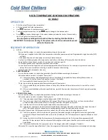
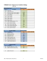
Example of Temperatures of Operation
Code
Description
Detail
Typical Values
(°F)
TLH
Temperature Limit High
The highest temperature at which all functions will stop.
120
DTH
Deviation Temperature High
Difference above Set Value that a timer starts. If temperature does not lower, then fault.
SP + Δ30=85
RH
Range High
Highest value that can be entered as a Set Value
80
DU2
Deviation Upper 2
Hysteresis value above Set Value plus 1°F
58
DU1
Deviation Upper 1
Hysteresis value above Set Value
57
SV
Setpoint Value
The desired temperature entered in the controller
55
DL1
Deviation Lower 1
Half of the hysteresis value below Set Value
54
DL2
Deviation Lower 2
Hysteresis value below Set Value
53
RL
Range Low
Lowest value that can be entered as a Set Value
44
DTL
Deviation Temperature Low
Deviated temperature value below Set Value which resets all cooling functions.
SP - Δ7=48
TLL
Temperature Limit Low
Lowest temperature which resets all cooling functions.
37
CTS
Cooling Hysteresis
The number of degrees from Set Value that cooling operations start and stop.
SP Δ 2
Communication Option via PLC RS-232 Communication
Via DVP14SS2 COM1 port
Register
Address
Description
Function
Com1 Port: RS-232
PLC Modbus address: 1
Data Length: 7 bit
Stop bits: 1
Parity: Even
Baud rate: 9600
D0
(Machine
mode)
1000hex
1 is Cooling Cycle mode.
2 is Pump Only mode.
3 is Off (selector switch is in OFF position).
Selector Switch Position
D1
1001 hex
SV
Set Value
D2
1002 hex
PV
Process Value
D3
1003 hex
Fault#
Fault #
D4
1004 hex
1 is Cooling Mode Status – OK
0 is Cooling Mode Status – Not Active
Cooling Mode Status
Summary of Contents for ACWC-180-EM-DR-LT-0-5
Page 35: ...Notes...

