SHEET #:
2
SHEET:
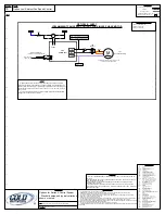
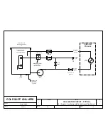
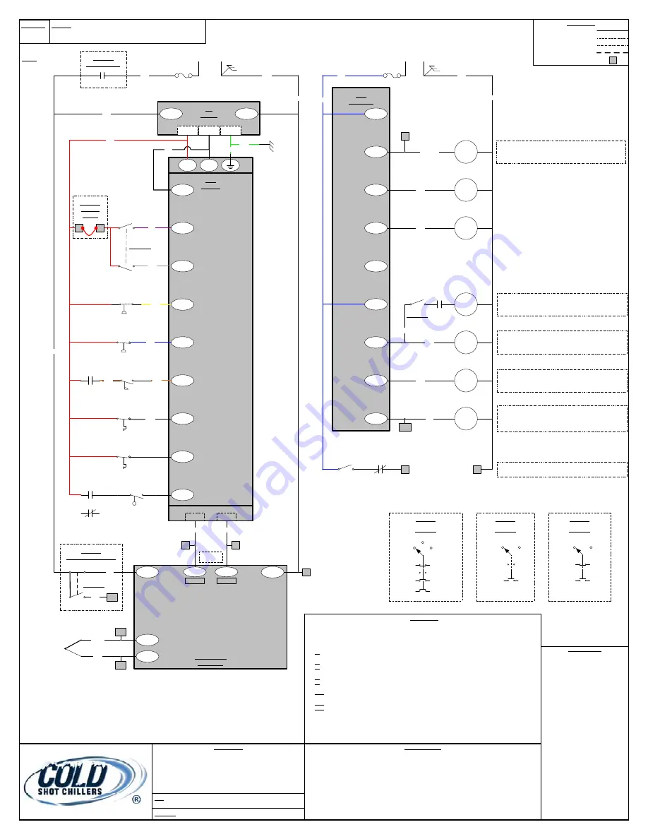
A1-Control
REF DATE:
January 8, 2016
DESCRIPTION
Options for Series A Control System
Standard setup and typical variations
shown or noted.
FILE:
DWG_Electrical-DeltaControl-SeriesA1-Options_010816.vsd
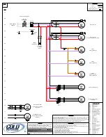
GENERAL NOTES
1. Circuit breaker(s) may be used in place of fuse(s).
2. WARNING-For continued protection against fire hazard replace fuses with the same type and rating only.
3. Unit must be permanently grounded and conform to N.E.C. & local codes.
4. Use copper conductors for field-wiring. Class 1, unless noted. All wire based on 105°C insulation wire, minimum.
5. Wire colors shown may differ from actual unit.
6. Drawing line item reference identification:
- Number in parenthesis near output is location of controlled items. First number is sheet #, second & third are line#.
- No underline indicates normally open (NO) contact, Underline indicates normally closed (NC) contact.
7. All intellectual property, including designs and programming logic are the property of Cold Shot Chillers and is not to be
copied or used without permission from Cold Shot Chillers.
8. Design, specifications, and components are subject to change without notice.
9. Options and alternate design and components may exist and are typically dependent on design and specific parts used
for the system.
LINE LEGEND
FACTORY SUPPLIED/INSTALLED
DETAILS
FACTORY OPTION
FIELD SUPPLIED/INSTALLED
TERMINAL BLOCK CONTACT #
#
09
10
11
LINE#
12
13
14
15
16
17
18
01
02
03
04
05
06
07
08
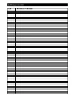
COMPONENT CODES
AUX
Auxiliary (contact block)
BZ
Buzzer
CC#
Compressor Contactor 1 or 2
CCH
Crankcase Heater
COM
Common
CR#
Control Relay:
CR1
CR for Cooling Mode Status
CR2
CR for Active Cooling On
CR3
CR for Chiller Pump functions
CR4
CR for Process Pump functions
CR5
CR for Remote ON/OFF Operation
CR6
CR for Tank Level Control
DB
Distribution Block
DT
Digital Temperature Controller
F
Fuse
F1/F2
Fuse 1 and 2 (Transformer Primary)
F3
Fuse 3 (120VAC Control Voltage)
F4
Fuse 4 (24VAC Control Voltage)
FC
Fan Contactor
FPS
Fan-Cycling Pressure Switch
FST
Flow Safety Thermostat
FZT
Freeze Safety Thermostat
GND
Ground
HG
Hot Gas
HPS
High Pressure Switch
L
Line
LAR
Low Ambient Relay
LAT
Low Ambient Thermostat
LFS
Liquid Flow Switch
LPS
Low Pressure Switch
LT1
Light 1 for Cooling Status – OK
LT2
Light 2 for Cooling Status – Fault Condition
M
Motor
MS
Motor Starter
NC
Normally Closed
NO
Normally Open
PC1
Pump Contactor 1 (Chiller Pump)
PC2
Pump Contactor 2 (Process Pump)
PLC
Programmable Logic Controller
PM
Phase/Voltage Monitor
PS
Power Supply
RC
Run Capacitor
SW1
Selector Switch (Pump/Off/Cooling)
SW2
Selector Switch (Process Pump)
SW3
Local/Remote Switch
TB
Terminal Block
TC
Thermocouple (Type J only)
TLH
Tank Level Switch – High
TLL
Tank Level Switch – Low
TLM
Tank Level Switch – Mid
TRAN
Transformer
Temperature
Controller
N
12
11
L
PLC
INPUTS
PLC
OUTPUTS
RED
BLK
TRAN1
PS
24VDC
HPS
VIO
GRA
YLW
X1
X0
X2
S/S
WHT
SW1-1
SW1-2
BRN
BLU
ORN
GRN
X3
X4
X5
X7
X6
BLK
BLK
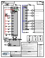
* PAGE NOTES
1. Control transformers must be wired/tapped for the appropriate incoming voltage. Depending on design, one dual
voltage or two independent voltages. Operation of system with improperly wired transformer is considered abuse
and resulting damage is not covered by warranty. Transformers may include breaker.
2.
PLC inputs
dependent on system design. 24VDC required to unused inputs.
3.
PLC outputs
dependent on system design:
Y0 - “Cooling Mode Status”. Only available when in cooling cycle and cooling circuit is in operational mode (not in
alarm condition).
Y2 - used on tandem compressor systems only.
Y3 - pump operation (for systems with internal chiller pump or output available for external pump) (optional).
Pump condition status relay or light (optional). Pump relay use dependent on design.
Y4 - hot gas solenoid or relay (optional).
Y5 - on when any compressor is on (used for fan contactor/relay “CR1” and/or liquid solenoid valve purposes).
4.
Switch identification
: “SW#” is switch ID. “SW#-#” is switch ID with position.
SW1 – Mode Selector switch (3 position to include 2 single NO contact blocks. Cooling Cycle may use double NO
contacts for aux purposes or additional stacked NO single block)
SW2 – Process Pump “ON/OFF” switch (2 position to include 1 single NO contact block)
SW3 – Local/Remote switch (2 position to include 1 single NC and 1 single NO contact block)
5. Delta controls with program A1##. (PLC and Temperature Controller must be programmed for system model/design.
6. Terminal blocks are dependent on system design. TBs may or may not be included in system.
7. RS-232 communication available. Refer to instruction guide.
8. Motor Starter auxiliary contacts used with motor starter/contactor combination models. Overload auxiliary contacts
used with overload models.
BLU
LPS
FZT
FST
RS-485
RED/WHT
BLK/WHT
LFS
24V
0V
See Fig1
120VAC
OPTION
Remote
On/Off
YLW
ORN
Y1
Y2
C1
C0
CC
1
CC
2
PC
1
GRN
Y3
HG
GRY
Y4
CR
2
Y5
-
Compressor #1 Contactor
Compressor #2 Contactor
OPTION: Hot Gas Solenoid (or Relay)
OPTION: Cooling Active - Control Relay (CR2) or
Fan Contactor (FC) and/or Liquid Line Solenoid
Valve
GRN
GRN
L
N
-24VDC
+24VDC
GND
Y0
13 14
PC1
PC
2
13 14
MS2
OPTION: PPC – Process Pump Control Contactor
PPR – Process Pump Control Relay
GRN
SW2
See Fig2
0VAC
(COM)
0VAC
(COM)
3
RED/WHT
CR
1
OPTION: Cooling Mode Status (OK) – Relay
ORN
TLL
(Option)
13 14
MS1
95 96
OL1
X4
X1
X3
X1
-
+
Twist
Wires
BLK
BLK
10
Data-
9
Data+
10
OPTION
Local/Remote Switch
SW3-2
SW3-1
BRN
13
VIO
WHT
9
8
7
BLU
“Remote”
FIGURE 3
SW3 Setup
SW3-2 (NO)
“Local”
1
2
SW3-1 (NC)
FIGURE 2
SW2 Setup
1
2
“OFF”
-1
“ON”
SW2-2 (NO)
1
0
2
FIGURE 1
SW1 Setup
SW1-1 (NO)
SW1-2 (NO)
“Pump Only”
“Cooling Cycle”
SW1-2 (NO)
(Aux)
“Cooling Cycle”
“OFF”
-0
OPTION: Cooling Mode Status (Fault)
11 12
CR1
4
5
SW1-2
(Aux)
24VAC
F4
TRAN1
PM
OPTION
Phase Monitor
BLK
F3
TC+
TC-
4
5
12
11
TC
White
Red
2
1
See Fig3
OPTION: CPC – Chiller Pump Contactor
CPR – Chiller Pump Relay
Summary of Contents for ACWC-180-EM-DR-LT-0-5
Page 35: ...Notes...

