background image

31

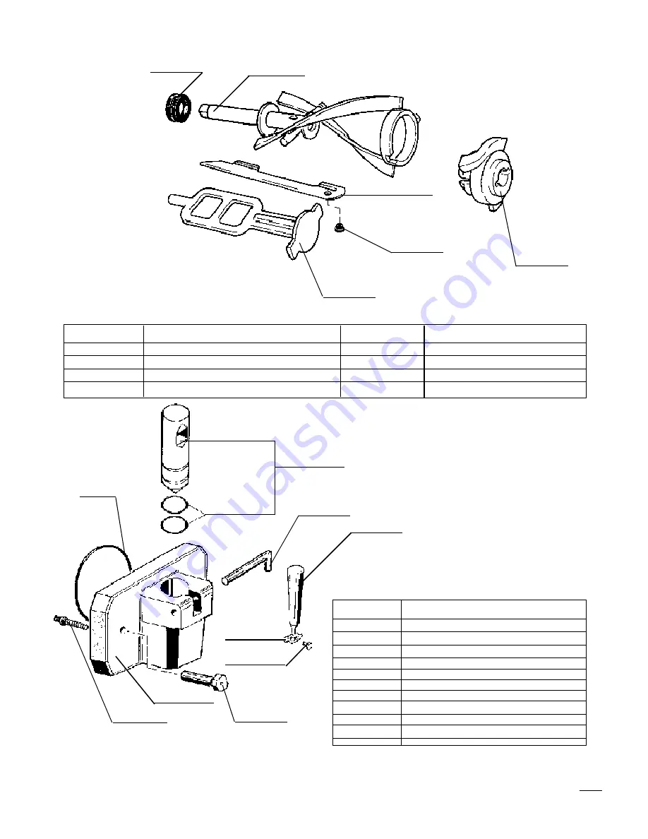
PARTS IDENTIFICATION

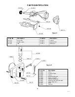
1685510

1642110

Figure C

  Code No.

Description

Code No.

Description

  1642110

End pusher

1641463

Scraper

. 1641464

Rubber spacer

1640520

Beater 4xD85

  1641641

Idler

1685510

Beater seal

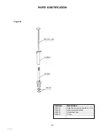
1685280

1656121

Figure D

1652022

1654201

1653080

1685260

1654010

  Code No.

Description

  1685260

O-ring

  1652022

Complete Piston

  1685280

O-ring

  1654010

Handle retaining rod

  1653320

Dispense Handle

  1653080

Piston activating cam

  1654201

Retaining knob, dispense head

  1651222

Spigot heady body

  1656121

Screw

  1654330

Stud bolt

1641641

1640520

1641463

1641464

1653320

1651222

1654330

Summary of Contents for UC 511 G

Page 1: ...39 UC 511 G Soft Serve Freezer SINGLE FLAVOR COUNTER MODEL OPERATION SERVICE MANUAL COLDELITE CORPORATION OF AMERICA 3760 INDUSTRIAL DR WINSTON SALEM N C 27105 TEL 910 661 9893 FAX 910 661 9895...

Page 2: ...of this Operation and Service Manual PLEASE READ IT CAREFULLY Keep it for future reference and most of all follow the instructions from the very time your machine is put into service Onthefollowingpa...

Page 3: ...2...

Page 4: ...CLEANING PROCEDURE 10 PART IV ASSEMBLING THE FREEZER 14 A Assembling the Beater Augers 14 B Assembling the Dispensing Head 15 C Assembling the Gravity Feed Tubes 17 PART V SANITIZING THE FREEZER 18 P...

Page 5: ...4...

Page 6: ...ff B Positioning the Machine 1 The freezer is shipped without legs installed To install the legs lift the freezer and screw the four legs into the bottom of the frame at each corner When the freezer i...

Page 7: ...panel the machine s wiring connection box can be found on the bottom of the frame and is labelled Connect Power Line Here The power line is first passed through the access hole located atthebottomdec...

Page 8: ...when full The MIX LEVEL SWITCH is located within the stainless steel plastic rod attached to the bottom of each mix tank L1 L2 L3 L5 L4 570 571 1 571 2 PART II EXPLANATION OF CONTROLS A Electronic Con...

Page 9: ...The Electric Control Panel located behind the upper rear panel of the unit contains the controlling circuit to the components of the machine This panel is to be accessed only by trained experienced t...

Page 10: ...rols temperature of the product in hopper and cylinder Controls and or energizes all the information or messages displayed on the monitor 6 FUSE protects 115 voltage line 7 The CURRENT TRANSFORMER mon...

Page 11: ...brushes 6 several packets of sanitizer and the OPERATIONAL MANUAL HELPFUL SUGGESTION Before proceeding with the disassemblyofthefreezer werecommendaplasticdishpanbe usedinwhichtoplacetheparts Thiswil...

Page 12: ...G EXTRACTOR to remove o rings as damage to the o ring and or part can result 3 Clean carefully the mix level device 4 Loosen and remove the two 2 dispensing head retaining knobs The knobs are removed...

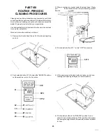
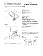
Page 13: ...tonoutofthedispenseheadwith the handle Using the O RING EXTRACTOR remove the piston o rings Each piston o ring groove is notched for easy insertion of the o ring extractor Turnthedispensingheadoverand...

Page 14: ...ly disassembled The parts should now be washed rinsed and sanitized 10 Wash all the parts in luke warm water 80 85 F using a mild detergent and the cleaning brushes provided in the START UP KIT DO NOT...

Page 15: ...ound the seal surface as shown below PART IV ASSEMBLING THE FREEZER Once the parts have been washed rinsed and sanitized the freezer is ready to be re assembled Prior to beginning the re assembly proc...

Page 16: ...aceandtheidlerisproperlyinstalled Rotatethebeater augeruntilyoufeelthedriveshaftengageand push the beater auger further back to properly seat B ASSEMBLING THE DISPENSING HEAD 1 Begin by gathering the...

Page 17: ...ubricate the O ring with the sanitary lubricant 2 First remount the end piston O rings onto the end pistons Simply roll onto the piston until they drop into the O ring notches 3 Once the O rings have...

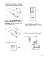
Page 18: ...knobs 8 HAND TIGHTEN the knobs B D C ASSEMBLING THE GRAVITY FEED TUBES 1 Begin by gathering the parts needed to assemble the gravity feed tube These parts include A the SPLASH GUARD B two 2 3 4 diame...

Page 19: ...be sanitized PART V SANITIZING THE FREEZER Prior to install the machine with your soft serve product the machine must be sanitized The frequency of cleaning and sanitizing cycles must comply with loc...

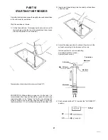
Page 20: ...ube out of the mix tank hole and lay it down in the tank This will allow the cylinder to completely fill with the sanitizing solution 3 Push selector button 571 2 to select the BEATER position Let the...

Page 21: ...s possible during the washing and sanitizing operations Excessive use will cause premature wear to the beater auger and cylinder Clean and sterilize the machine as described in chapter 8 daily or ever...

Page 22: ...he dispense handle be opened to allow any residual sanitizer to be chased out by the mix entering the cylinder Place a cup under the dispense head to catch any residual sanitizer 2 3 oz is sufficient...

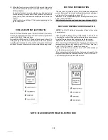
Page 23: ...me controlled refrigerated system Everytwo 2 minutestherefrigerationsystemisenergized and runs for 25 seconds when above 60 F Below 60 F the refrigeration system is energized and runs for 25 sec every...

Page 24: ...besureyouwillneverhavetopauseinselling ice cream even during peak times STAND BY During long pauses in ice servings press button pos 572 2 PUSH TO SELECT to select STAND BY You will save significantly...

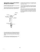
Page 25: ...run yield by letting more or less mix enter the freezing cylinder by manually regulating the valve The plunger splash guard keeps the mix from splashing on the mix tank cover and serves as a device to...

Page 26: ...follows 1 Remove the Gravity Feed Tubes Pull the tubes straight up and out 2 Push selector button 571 2 to select the BEATER position Let the machine run for 4 to 5 minutes 3 Place a container or buck...

Page 27: ...out Amperage 5 A Overload cutout Amperage 5 5 A Voltage 115 Volt Beater rotation counter clockwise Electronic Hard O Matic Control Adjustment If the H O M needs to be recalibrated proceed as following...

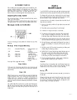
Page 28: ...box panels AlwaysturntheSelectorSwitchtotheOFFposition Also turnoff the Disconnect Switch on the electrical supply line before exposing any electrical connections and or moving parts such as belts pu...

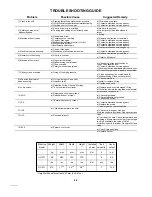
Page 29: ...c Check water flow a Install or replace O ring b Tighten hand knob a Replace any worn or damaged O ring b Close liquid hole in feeding tube draw several portions and reopen hole a Check spigot head b...

Page 30: ...0 Mix tank cover 1722620 Touch panel 1746020 Spring 1904390 Rear panel 1746010 Cover rear drip tray 1902300 Left side panel 1906350 Front panel 1745210 Plastic drip chute 1720710 Proximity switch 1745...

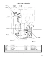
Page 31: ...B Figure F PARTS IDENTIFICATION Code No Description Code No Description 3201321 Motor 1612150 Connecting flange 1602300 Gearbox with motor 1664500 SL Sensor mix level 1612150 1664500 Figure C 3201321...

Page 32: ...0 Beater seal 1685280 1656121 Figure D 1652022 1654201 1653080 1685260 1654010 Code No Description 1685260 O ring 1652022 Complete Piston 1685280 O ring 1654010 Handle retaining rod 1653320 Dispense H...

Page 33: ...RTS IDENTIFICATION Figure E 1638090 1638400 1685430 1638150 L 225 Code No Description 1638150 Splash guard gravity feed tube L 225 1638090 Sleeve gravity feed tube 1638400 Gravity feed tube 1685430 O...

Page 34: ...ode No Description 1727580 Expansion Valve Cylinder 1727850 Orifice for 1727580 3301020 Compressor 1727280 Solenoid valve body 3306390 Pressure switch 1724800 Solenoid valve coil 3203250 Fan motor 172...

Page 35: ...90 TRI Transformer 1722990 TR2 Transformer 24 11 Volt 1727720 Microprocessor Eprom 1722020 CPU Electronic board 1722350 MIP Safety magnetic switch 1722400 Suppressor elect interference 3213500 TRA Cur...

Page 36: ...35 WIRING DIAGRAM...

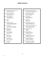
Page 37: ...que Transformador de corriente TTA Beater motor contactor Contacteur moteur malaxeur Telerruptor motor agitador TTC Compressor motor contactor Contacteur moteur compresseur Telerruptor motor compresor...

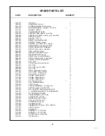
Page 38: ...ting cam 1 1664030 NUT M16 1 1664500 STEM Electronic level control 1 1685430 OR 2062 2 1685260 OR 6362 see 3410090 2 1685280 OR 4106 4 1685510 SEAL beater shaft Hytrel 2 1711480 INS PLATE Wago 260 361...

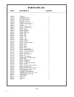
Page 39: ...310 DECAL EVV 1 2116320 DECAL EVC 1 2117030 DECAL Heater 1 2117060 DECAL NSF 1 2117070 DECAL warning safety 2 2117080 DECAL DANGER ELECTRIC 2 2117160 DECAL caution moving parts 1 2117310 DECAL Soft so...

Reviews: