6
C) Electrical Requirements
All wiring installed to operate this freezer must be in accordance
with the National Electrical Code and/or local electrical codes,
rules and regulations. The machine must be properly grounded.
It is recommended the power supply be installed by a licensed
electrician.
Voltage UC 511: 115 Volts
Total Running Amperage FLA: 18 Amps.
Fuse Size: 20 Amp. Max.
Wire Size (50 Ft. Max.): # 10
Power Supply must be adequate to meet requirements at all
times. Voltage fluctuations, with the machine in operation, should
not exceed ± 5% of the normal or rated voltage.
Adequate Wiring must be provided with respect to wire size or
gauge. Unless otherwise required by the local Electrical Code,
the same size wire gauge at the machine junction box should be
used for direct power line. A separate circuit breaker with
adequate fuse protection should be employed.
An unfused disconnected switch or a properly sized plug and
receptacle within 6 feet of the freezer, is recommended.
Coldelite freezers are equipped with protection for the beater
motor. Should the line voltage drop, or in the unlikely event a
short circuit occurs, the overload protector will automatically
disconnect the starter and the machine will stop immediately so
that no permanent damage can be caused to the motor.
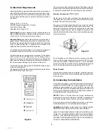
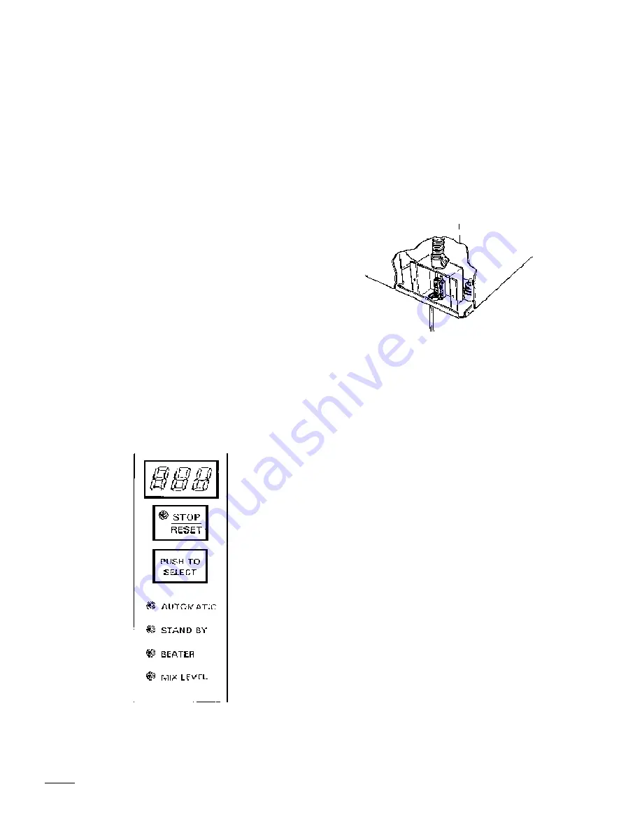
To restart the freezer, depress the STOP/RESET button located
on the front switch pad.
The heater protection must cool down for several minutes before
the RESET will operate. See Fig. 4.
The compressor is also internally protected. If the Klixon protector
trips due to an overload, again the protector must first cool down
for several minutes before the compressor can be restarted.
Electrical Connections
(Ref. Fig. 5)
Having removed the right side panel, the machine’s wiring
connection box can be found on the bottom of the frame and is
labelled “Connect Power Line Here”.
The power line is first passed through the access hole located
at the bottom deck directly below the wiring connection box. The
power line may then be connected to the machine’s power lines
and wiring connection box. Upon completion, the power line
should be fastened to the wiring connection box with appropriate
electrical hardware.
In all installations, the machine must be properly grounded.
Since all high voltage components (controls are 24 volts) are
connected by means of flexible conduit, or cord, adequate
ground continuity is assured by running and fastening a ground
line to the machine junction box ground lug. (Ref. Fig. 5).
Beater Rotation
After electrical connections are completed, check the rotation of
the beater. It should be counter clockwise when facing the front
of the machine.
D) Completing the Installation
On the following pages, you will find important information and
procedures which describe the proper installation, sanitizing,
operation and maintenance of your COLDELITE machine. We
feel certain that your full compliance with these instructions will
assure you of excellent performance, trouble-free operation and
a profitable business for years to come.
NOTICE: Failure to closely follow set-up and maintenance
procedures can void your warranty. Coldelite Corporation will
not be responsible for any machine not properly maintained.
In the event this unit should malfunction, please contact your
Coldelite Distributor or an authorized service agency.
WARNING:EXTREME CARE MUST BE TAKEN WHEN
REMOVING SIDE, REAR OR CONTROL BOX PANELS.
ALWAYS TURN THE MACHINE TO THE OFF POSITION. ALSO
TURN OFF THE DISCONNECT SWITCH ON ELECTRICAL
SUPPLY LINE BEFORE EXPOSING ANY ELECTRICAL
CONNECTIONS AND/OR MOVING PARTS, SUCH AS BELTS,
PULLEYS, FAN BLADES AND BEATER.
Figure 5
Figure 4


