24
B) Gravity Fed Machines
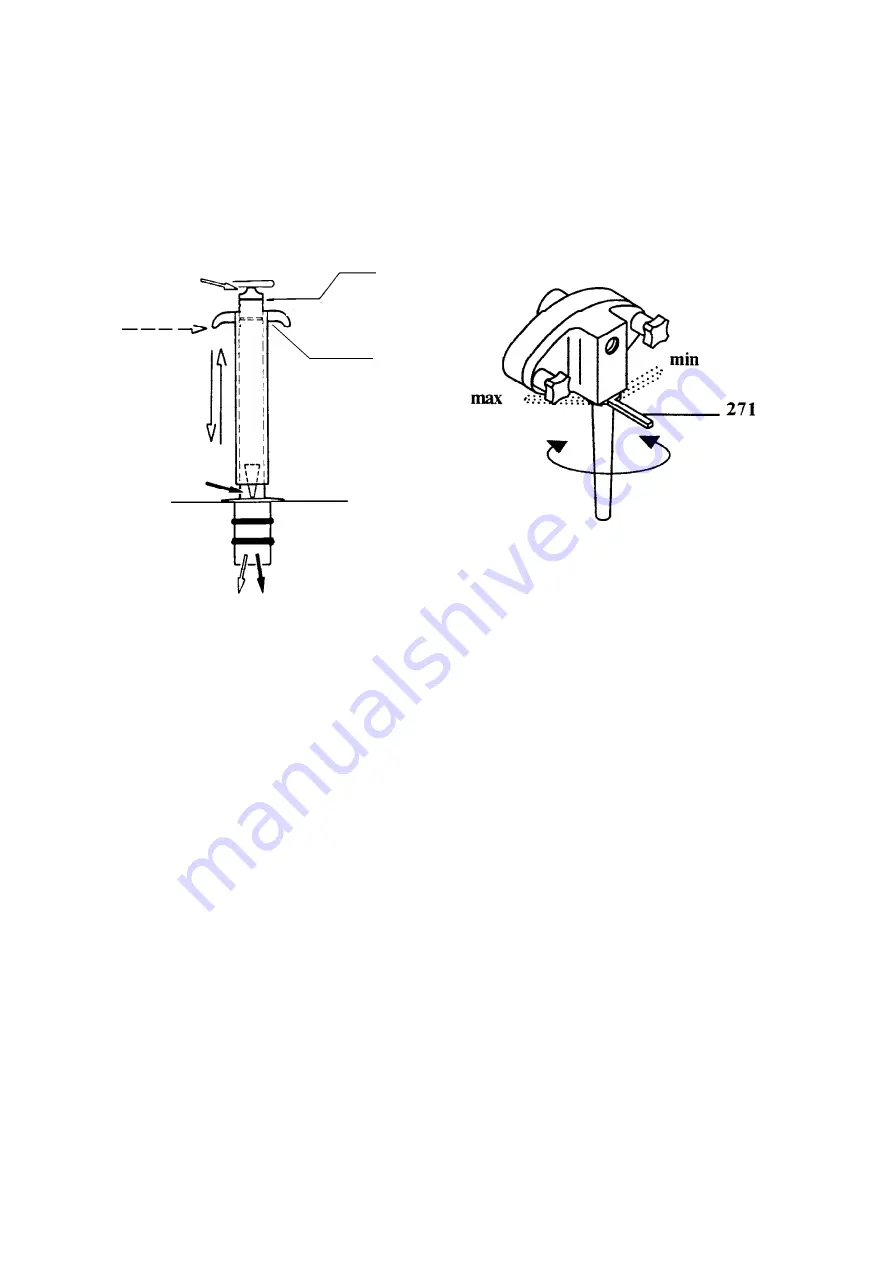
The gravity feed tube consists of two tubes, one
sliding inside of the other, and a center splash
guard. The inner tube blends the flow of air and
mix into the freezing cylinder. Air enters through
the top of the tube, mix through the bottom.
(Refer to figure 9)
Figure 9
The outer tube is actually a regulating valve. Lif-
ting or closing this outer tube changes the hole
opening size on the inner tube which allows more or
less mix to enter the freezing cylinder. Since the air
inlet hole size does not change, the air inlet is
constant.
You can vary the overrun (yield) by allowing more
or less mix to enter the cylinder by changing. You
do this by opening or closing the outer regulator
sleeve setting on the inner feed tube.
The inner splash guard keeps mix from splashing
the underside of the mix tank cover as well as elimi-
nate clogging of the feed tube.
The draw rate, portion size, and mix viscosity will
determine the final regulating sleeve setting. Our
standard setting is 2 to 3 notches up from the
bottom. Open the outer tube to increase the mix
amount. Close the outer tube to decrease the mix
amount. Adjust for your specific application.
C) Pump Fed Machines-Operation
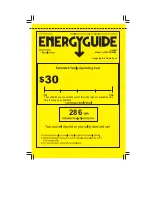
The mix injection pump runs whenever the beater
drive motor is turning. To regulate the amount of
mix being injected into the cylinder, pivot the pump
suction tube either to the right (less mix/more air)
or to the left (more mix/ less air). (Refer to figure
10)
Figure 10
The air intake is through the front two holes of the
pump cover. Since the two air inlet holes are fixed,
the air intake is constant. To adjust your overrun
(yield) you must regulate the amount of mix being
pumped into the cylinders. The mix pump suction
tube will change the orifice size on the tube to
allow either more or less mix to be pumped into the
cylinder.
You will also have to adjust your pump suction
tube during daily operation to either a larger (Left)
or smaller (Right) orifice setting depending on your
draw rate and product viscosity.
For heavy draw rates and / or thick viscosity
mixes, a setting of center, one, two, or three
positions to the left of center will be necessary in
order to operate the machine properly.
For light draw rates and / or thin viscosity mixes, a
setting of center, one, or two positions to the right
of center will be necessary.
The “Normal” operating position for the suction
tubes on this freezer is either one position to the
left, center, or one position to the right.
Mix Intake
Max. Fill Level
Air Intake
Maximum
Standard


