8
3) Beater Motor Overload Protector -
(Left/Right) –
Monitors the current draw of the beater drive
motor. If the motor draws excessive amperage, the
overload will trip and Alarm 1 (RtA) will be
displayed on the touch pad monitor.
4) Main Transformer – This transformer reduces
the incoming line voltage to 24 volts for the primary
control circuit.
5) Electronic Control Boards –
(Left / Right) –
These
boards control and monitor
ALL
functions of the
machine.
6) Safety Fuse – This fuse protects the high voltage
side of the main transformer in the event of a short
circuit. If tripped, all of the machines controls and
touch pads will be inoperative.
7) Current Monitoring Transformer –
(Left / Right) –
These transformers monitor the current draw of the
beater drive motors.
8) Secondary Transformer – This transformer
reduces the voltage from 24 volts to 11 volts for the
electronic control circuit.
F) Other Controls
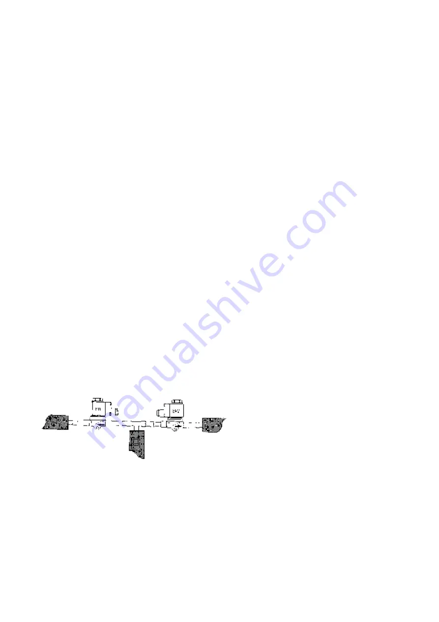
1) Refrigeration Solenoid Valves – These valves are
located behind the front panel. These valves are
used to control the flow of refrigerant to the
cylinders or mix storage tanks. These valves are
designated with EVC for each cylinder and EVV
for the mix storage tank. (Refer to Figure 8)
Figure 8
2) High Pressure Safety Switch – In the event of
restricted airflow (Air Cooled) or restricted water
flow (Water Cooled), this switch will turn off the
compressor contactor.
While tripped, the beater motors will continue to
run until the refrigerant pressure is reduced enough
to reset the safety switch. After resetting, both the
compressor and motor(s) will resume running.


