background image

2

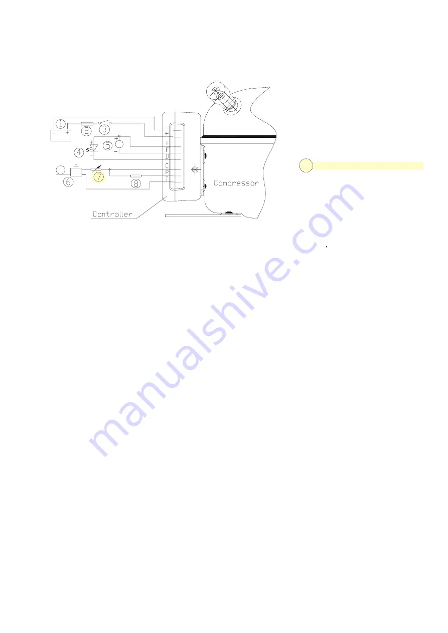
5.1.1    The Controller is connected to the battery  d irectly, wrong connect the poles doesn t destroy 

the compressor and controller, but the compressor d o not work; 

5.1.2    The fuse must be connected  in the + cable to  protect controller, which close to the power 

supply, 15A fuse for 12VDC and 7.5A fuse for the 24 VDC are recommended; 

5.1.3    If a main switch is used, it should be rated  to current of min. 20A; 

5.1.4    To prevent voltage dropping, please avoid ex tra junction in the power supply system. 

5.1.5    A  Light  Emitting  Diode(LED)  for  compressor  o peration  monitoring  can  be  connected  

between the ter and D . 

Operational errors will cause the LED  to  flash a  nu mber of times.  The number of flashes 

depends on what kind of operational error was recor ded. Each flash will last 1/4 second and 

each error will repeat every 4 seconds. Operational  errors show by Table 5, please see it in 

page 6. 

5.1.6    If a cooling fan is used. It must be connect ed

    to electronic unit ter and F, only use 

12VDC fan , no matter what power supply you are usi ng; 

5.1.7    A Thermostat is connected between the termin al C and T of the electronic unit. It will start 

or stop the running of compressor automatically; 

5.1.8    A Resistor can be connected between terminal  C and T, it allows you to adjust the speed of 

the compressor, the  relationship  between the resist or and the compressor  speed shown  by  

Table 3; please see it in page 3. 

5.1.9    To  ensure  sufficient  battery  power  for  co mpr essor  and  avoid  permanent  damage  to  the  

battery  because  heavy  discharge.  A  battery   protecti on  resistor  is  connected  between  

terminal C and P, the different resistor will get t he different voltage protection, the details is 

showed by Diagram 4; 

PROCOLD S.r.l. - ITALY- 13043 CIGLIANO (VC)

C/so Umberto,58 - Tel (+39) 0161 42 44 52 Fax (+39)  0161 4 2 40 92 
                     www.procold.it      info@proco ld.it

5 Controller 

 5.1


Wiring


The  Compressors                                               are equipped

      with a brushless direct current 

motor which  is controlled  by  an  Attached  Controller,   the wiring is shown as following drawing:

 TD35 VS

 and 

TD50 VS  

1 Battery 

2 Fuse 

3 Main Switch (optional) 

4 LED (optional) 

5 12V DC Cooling Fan (optional) 

6 Thermostat 

7 Resistor for presetting speed (optional)  C-T

8 Resistor for presetting battery protection 

voltage (optional) C-P

Rev. 2.0 27/02/2019

Summary of Contents for TD35 VS

Page 1: ...PROCOLD S r l ITALY 13043 CIGLIANO VC C so Umberto 58 Tel 39 0161 42 44 52 Fax 39 0161 42 40 92 www procold it info procold it TD35 VS TD50 VS Technical specifications Compressor for R134a 12 24V DC ...

Page 2: ...rpm Capacity W Input Power W Operating Current A C O P W W 1 1 Sound Level dB A Vibrancy Acceleration m s2 0 65 Operating Voltage V DC Cooling Static or Fan cooling Lubricant Polyester Lube Vol ml 5 Weight kg 4 3 Weight of Controller kg 0 40 Motor Type BLDCM Refrigerant R134a Throttling Device Capillary Power V D C 12 24 Test conditions Evaporating Temp 23 3 Suction Temp 32 2 Condensing Temp 54 4 ...

Page 3: ...are using 5 1 7 A Thermostat is connected between the termin al C and T of the electronic unit It will start or stop the running of compressor automatically 5 1 8 A Resistor can be connected between terminal C and T it allows you to adjust the speed of the compressor the relationship between the resist or and the compressor speed shown by Table 3 please see it in page 3 5 1 9 To ensure sufficient ...

Page 4: ...ltage V 0 9 6 10 9 17 0 21 3 22 7 31 5 1 6 9 7 11 0 17 0 21 5 22 9 31 5 2 4 9 9 11 1 17 0 21 8 23 2 31 5 3 6 10 0 11 3 17 0 22 0 23 4 31 5 4 7 10 1 11 4 17 0 22 3 23 7 31 5 6 2 10 2 11 5 17 0 22 5 23 9 31 5 8 2 10 4 11 7 17 0 22 8 24 2 31 5 11 10 5 11 8 17 0 23 0 24 5 31 5 14 10 6 11 9 17 0 23 3 24 7 31 5 18 10 8 12 0 17 0 23 6 25 0 31 5 24 10 9 12 2 17 0 23 8 25 2 31 5 33 11 0 12 3 17 0 24 1 25 5...

Page 5: ...he refrigeration system has been too heavily loaded or if the ambient temperature is high than 55 the controller will run too hot 4 Minimum motor speed error if the refrigeration system is too heavily loaded the motor speed is lower than 1850 rpm 3 Motor start error The rotor is blocked or the system pressure is too high 2 Fan over current cut out The operating current of cooling fan is more than ...

Page 6: ...ressor the pressure in the compressor could not more than 0 49MPa 8 6 Do not operate the compressor before polyester is charged 8 7 The refrigerant charge should be less than 200g 8 8 The interval of compressor operation Operation is more than 3 minutes and the stoppage is more than 3 minutes too 8 9 Special attention Do not use the compressor as a vacuum pump and do not start it under vacuum stat...

Page 7: ...VS TD50 VS PROCOLD S r l ITALY 13043 CIGLIANO VC C so Umberto 58 Tel 39 0161 42 44 52 Fax 39 0161 42 40 92 6 www procold it info procold it CONTROLLER COMPRESSOR PROCESS Ø 6 20 SUCTION Ø 6 20 DISCHARGE Ø 5 15 DIMENSIONS COMPRESSOR Rev 2 0 27 02 2019 ...

Reviews: