background image

Section 6

6-4         Polystat

Cole Parmer

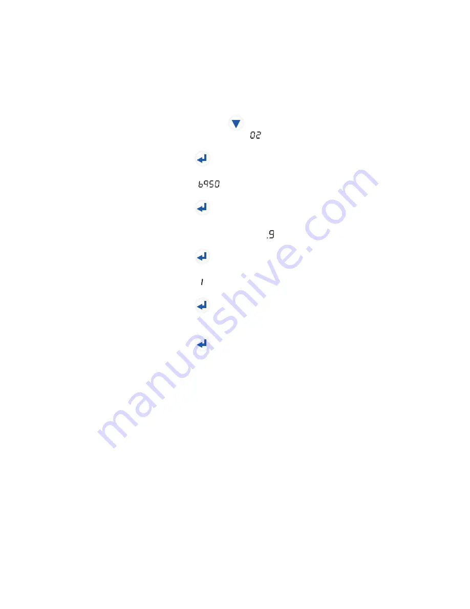
The controller can display the installed software version number. For 

example, for a chiller with software version 

026950.9A

:

1. Ensure the chiller is running normally and displaying recirculating fluid 

temperature.

2. Press and hold 

for at least 20 seconds. The display will show the first 

two digits, for example,   .

3. Press 


The display will show the remaining digits to the left of the decimal, for 

example, 

.


4. Press 


The display will show the decimal point and the digit to the right of the 

decimal point, for example, .

5. Press 


The display will show the revision letter, as its equivalent number, for 

example,    = A.

6. Press 


Disregard this display.

7. Press 


The display returns to the recirculating fluid temperature.

Displaying Software


Version Number

Summary of Contents for 12911-00

Page 1: ...Installation Operation Basic Maintenance High Capacity Recirculating Chillers Manual P N U01177 Rev 04 04 2012 Label ...

Page 2: ... ...

Page 3: ...e Nameplate 2 9 Approved Fluids 2 9 Wetted Materials 2 9 Section 3 Installation 3 1 Ventilation 3 1 Electrical Requirements 3 1 Plumbing Requirements 3 2 Process Fluid Requirements 3 3 Compatibility with Approved Fluids 3 4 Process Water Quality and Standards 3 5 Filling 3 6 Water Treatment Kit 3 7 Section 4 Operation 4 1 Controller 4 1 Start Up Shut Down 4 2 Circuit Protector 4 2 Start Up 4 2 Set...

Page 4: ...5 1 Condenser 5 1 Fluid Maintenance 5 1 Reservoir 5 1 Pump Strainer 5 2 Hoses 5 2 Temperature Sensor rdt1 Calibration 5 3 Section 6 Troubleshooting 6 1 Error Codes 6 1 Checklist 6 2 Controller PID Values 6 3 Displaying Software Version 6 4 Flow Diagram Declaration of Conformity ...

Page 5: ...nd a minimum of 115 psi Before using any fluid or performing maintenance where contact with the fluid is likely refer to the manufacturer s MSDS for handling precautions 2 Ensure the reservoir drain plug on the back of the unit is in place and that all plumbing connections are secure Loosen the two thumbscrews securing the reservoir cover to the unit Ensure the fluid filter is securely in place in...

Page 6: ...ature The controller will not allow you to enter a setpoint closer than 2 C of either temperature alarm setting Trying to use a setpoint within 2 C causes the appropriate indicator to flash and sounds the audible alarm twice Once the desired setpoint is displayed press to confirm the change The display will rapidly flash the new value for a short period and then return to the recirculating fluid t...

Page 7: ...08 EC Electromagnetic Compatibility Directive EMC EN61326 1 2006 Electrical equipment for measurement control and laboratory use EMC requirements 2006 95 EC Low Voltage Directive LVD EN61010 1 2001 Safety requirements for electrical equipment for measurement control and laboratory use general requirements WEEE This product is required to comply with the European Union s Waste Electrical Electronic...

Page 8: ...the purchase price pain therefor nor shall Distributor be liable for any claims losses or damage of any third party or for lost profits or any special indirect incidental consequential or exemplary damages howsoever arising even if Distributor has been advised of the possibility of such damages The line cord it is located under the shipping crate s lid Do not discard the lid until the cord is loca...

Page 9: ...the chiller s enclosure The voltage magnitude is significant enough to constitute a risk of electrical shock This label indicates read the manual NOTE The chiller s equipment design incorporates a complete sheet metal enclosure for personnel protection from mechanical and electrical hazards Observe all warning labels Never remove warning labels The chiller construction provides protection against ...

Page 10: ...rosive or flammable fluids with this chiller Use of these fluids will also void the manufacturer s warranty When using a process fluid mixture of ethylene glycol and water or propylene glycol and water check the fluid concentration and pH on a regular basis Changes in concentration and pH can impact system performance See Section 3 Never operate damaged or leaking equipment Never operate the chill...

Page 11: ...ible to ensure the reservoir overflow located on the rear of the chiller is connected to a suitable drain Refrigeration The chiller s refrigeration system is sealed and requires no lockout tagout Remove any isolation devices before starting the chiller Chemicals Prior to decontamination procedures should be developed and employed to minimize or mitigate opportunities for exposure to chemicals pres...

Page 12: ...1 4 Polystat Section 1 Cole Parmer ...

Page 13: ...ontroller It is designed for continuous operation and for indoor use in accordance with all the procedures and requirements stated in this manual Specifications 60 Hz units The MD pump is only available in 12911 12 14 Pumping capacity pressure values are differential pressures between the inlet and the outlet of the unit Cole Parmer Catalog Number Polystat I Polystat II Polystat III Process Fluid ...

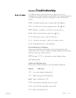
Page 14: ...esult in a loss of cooling capacity and potential damage to the chiller Cole Parmer reserves the right to change specifications without notice Cooling Capacity A B C 10 0 10 20 30 C 20 30 40 50 60 70 80 F Temperature Setpoint Cooling Capacity BTU Hr Watts 8000 6000 4000 2000 2500 2000 1500 1000 500 Catalog A 12911 16 20 B 12911 04 08 12 C 12911 00 See catalog cross reference guide below Catalog Cr...

Page 15: ...ltitude or operating voltages will affect performance See Section 3 Maximum no flow pressure can vary by as much as 10 psi Cole Parmer reserves the right to change specifications without notice Flow Rate 5 10 15 LPM 1 2 3 4 GPM 16 12 8 4 1 00 0 75 0 50 0 25 Bar PSID Pressure Pumping Capacity Positive Displacement Pumps Pumps PD1 PD2 Pumping Capacity Magnetic Drive Pumps MD Using water at 20 C Cole...

Page 16: ...ystat Cole Parmer Polystat I II Dimensions inches centimeters Side View 2 1 4 5 8 23 5 8 60 0 7 16 1 2 1 8 0 3 24 7 16 62 0 2 1 2 6 4 11 15 16 30 4 1 1 8 2 9 18 3 8 46 7 Front View 14 3 16 36 1 1 8 0 3 1 4 0 6 11 16 1 7 ...

Page 17: ...ifications without notice Top View Rear View Process Inlet 1 2 FNPT Brass Process Outlet 1 2 FNPT Brass 3 3 4 9 5 4 7 8 12 4 12 3 4 32 4 16 13 16 42 7 18 5 8 47 2 3 1 2 8 9 2 7 16 6 2 1 1 8 2 9 1 3 8 3 5 Process Drain 1 2 FNPT Brass DRAIN DRAIN Power In Circuit Protector 12 3 4 32 3 6 3 16 15 7 Fill and Pump Strainer Access ...

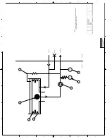
Page 18: ...2 6 Polystat Cole Parmer Polystat III Dimensions inches centimeters Side View 2 1 4 5 8 23 5 8 60 0 1 8 0 3 28 5 8 72 7 2 1 2 6 4 15 1 16 38 2 1 2 6 18 5 16 46 4 Front View 17 5 16 44 0 1 8 0 3 3 16 0 5 11 16 1 7 ...

Page 19: ...fications without notice Top View Rear View 3 3 4 9 5 5 1 16 12 9 15 7 8 40 3 21 1 16 53 4 22 7 8 58 1 1 9 16 3 9 3 1 16 7 7 1 1 4 3 2 2 3 8 6 1 Process Drain 1 2 FNPT Brass DRAIN DRAIN Power In Circuit Protector Process Inlet 1 2 FNPT Brass Process Outlet 1 2 FNPT Brass 9 1 8 23 2 6 15 16 17 6 Fill and Pump Strainer Access ...

Page 20: ...um temperature for the air entering the ThermoChill is reduced by 1 C per 1 000 feet above sea level In addition cooling capacity is reduced 1 2 per 1 000 feet above sea level Maximum relative humidity 80 for temperatures up to 31 C decreasing linearly to 50 relative humidity at 35 C Model Input Voltage Rating Frequency Phase Pump Current Rating Line Cord Plug Polystat I 115VAC 60Hz 1Ø PD1 9 8 A 5...

Page 21: ...luids Fluorocarbon EPDM Nitrile PPS BUNA N Sample Nameplate Cole Parmer 1 800 323 4340 BOM XXXXXXXXXXXX S N XXXXXXXXX POLYSTAT XXX 115V 60HZ 1PH X X A R134A XXX OZ HI XXX PSIG LOW XXX PSIG 1 1 Cole Parmer Instrument Company 625 East Bunker Court Vernon Hills IL 60061 1 800 323 4340 Filtered Single Distilled water 0 75 Laboratory Grade Ethylene Glycol Water 0 75 Laboratory Grade Propylene Glycol Wa...

Page 22: ...Section 2 2 10 Polystat Cole Parmer ...

Page 23: ...e variations between ambient and setpoint temperatures and or long plumbing lengths may require additional insulation The front of the chiller needs a minimum clearance of 24 The rear and sides should also be clear of obstructions Air will enter the front of the system and exit through the sides and rear Ventillation CAUTION Electrical Requirements The chiller construction provides protection agai...

Page 24: ...process OUTLET and process INLET Connect the process OUTLET to the fluid inlet on your application Connect the process INLET to the fluid outlet on your application Ensure all connections are secure and that the proper sealant lubricant for the fitting material is used If Teflon tape is used ensure the tape does not overhang the first thread as it could shred and get into the fluid Keep the distan...

Page 25: ...ere contact with the fluid is likely refer to the manufacturer s most current MSDS for handling precautions EG is also hygroscopic it will absorb water from its environment This can affect the freezing point and boiling point of the fluid over time and may result in system failure When using a process fluid mixture of ethylene glycol and water or propylene glycol and water check the fluid concentr...

Page 26: ...s in the fluid supply Corrosion and degradation of the circulation components can result from concentration ratios that are too high Contact our customer support for additional information Uninhibited Laboratory Grade Ethylene Glycol Water Ethylene glycol is used to depress the freezing point of water as a coolant We recommend not using the uninhibited no corrosion additives ethylene glycol It is ...

Page 27: ...ventually the pitting will become so extensive that refrigerant will leak into the water reservoir As an example raw water in the United States averages 171 ppm of NaCl The recommended level for use in a water system is between 0 5 to 5 0 ppm of NaCl Recommendation Initially fill the tank with distilled or deionized water within a range of 1 3 MΩ cm It is acceptable to have the fluid drop to the o...

Page 28: ...in the bottom of the reservoir Slowly fill the reservoir with clean process fluid until the fluid reaches the reservoir s lip Since the reservoir capacity may be small compared to your application and air may need to be purged from the lines have extra cooling fluid on hand to keep the system topped off when external circulation is started NOTE Failure to keep the reservoir full to the lip will re...

Page 29: ...rvice with optimal efficiency for the life of the chiller The kit includes a biocide and corrosion inhibitor capable of treating up to ten gallons of application water and is designed to provide protection for a period of six months This kit is compatible with the following fluids Filtered Single Distilled Water Uninhibited Laboratory Grade Ethylene Glycol Water Uninhibited Laboratory Grade Propyl...

Page 30: ...Section 3 3 8 Polystat Cole Parmer ...

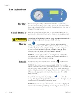
Page 31: ...rical values Indicates refrigeration system status It illuminates to indicate the refrigeration system is removing heat from the cooling fluid As the operating temperature approaches the temperature setpoint the LED will flash The indicator is off when heat is not being removed When illuminated the controller is displaying the user adjustable setpoint The setpoint is the desired process fluid temp...

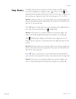
Page 32: ...ecirculating pressure gauge will display the pump operating pressure NOTE If on start up the chiller s recirculating fluid is outside either temperature limit the chiller will operate but the appropriate indicator will flash until the fluid is within the limit To display change the setpoint use the arrow keys will illuminate NOTE If the arrow keys are not pressed again within 10 seconds the displa...

Page 33: ...od and then will illuminate NOTE If the value is not confirmed within 10 seconds the display will return to the recirculating fluid temperature and ignore any changes With illuminated the display will flash the current high limit value If desired use the arrow keys to change the value The high end range is 10 C to 35 C NOTE If the arrow keys are not pressed within 10 seconds the display will retur...

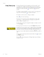
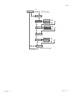
Page 34: ...hange The loop is used to determine how the chiller will react when a fault occurs either shut down or continue to run The chiller is shipped configured to run It is also used to configure the temperature displays to indicate to a tenth of a degree The loop can also be used to set the controller s PID parameters Cole Parmer recommends that only a qualified technician change PID parameters Incorrec...

Page 35: ...Section 4 Polystat 4 5 Cole Parmer FLt tEnt Sond CooL Stor on on on oFF oFF oFF Accept All Changes tunE XX X HOLD WITHIN ONE SECOND PRESS THE DOWN ARROW ...

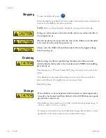
Page 36: ...fore using any fluid or performing maintenance where contact with the fluid is likely refer to the manufacturer s MSDS for handling precautions The drain port a 1 2 brass Female NPT plug is located on the rear of the chiller After draining we recommend inserting a wet vac into the reservoir and inlet outlet lines to thoroughly remove any excess fluid Reinstall the plug CAUTION CAUTION If the chill...

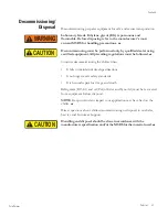
Page 37: ...egulations must be followed Consider decommissioning the chiller when It fails to maintain desired specifications It no longer meets safety standards It is beyond repair for its age and worth Refrigerant R134A and oil Polyol Ester and Syno Ad must be recovered from equipment before disposal NOTE Keep in mind any impact your application may have had on the chiller Direct questions about chiller dec...

Page 38: ...Section 4 4 8 Polystat Cole Parmer ...
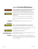
Page 39: ... parts listed below Clean the chiller s surface with a soft cloth and warm water only Failure to clean the condenser filter will cause a loss of cooling capacity and lead to premature failure of the cooling system Clean the filter with a soft bristle brush When it is time for a more thorough cleaning blow compressed air on the condenser to clean it The condenser fins are very sharp Check the fluid...
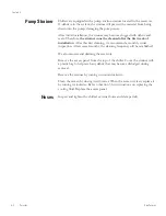
Page 40: ...mend a monthly visual inspection After several months the cleaning frequency will be established We also recommend draining the reservoir Remove the access panel from the top of the chiller Cover the strainer with a plastic bag to help catch any debris that may become dislodged during removal Remove the strainer by turning it counterclockwise Clean the screen by rinsing it with water When the scre...

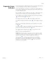
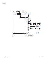
Page 41: ... will read rtd1 To calibrate the high end temperature press and the display will read r1H Press again and the display will flash between r1H and the current probe temperature Use and to adjust the r1H display Once the display temperature matches the reference thermometer press twice Press until Stor is displayed press to accept the new value Repeat for the low end temperature r1L NOTE Both the hig...

Page 42: ...Section 5 5 4 Polystat Cole Parmer Accept All Changes CAL HOLD rtd1 r1H r1H XX X XX X r1L r1L Stor tunE XX X WITHIN ONE SECOND PRESS THE DOWN ARROW HOLD ...

Page 43: ... comm check connections Asynchronous comm contact our customer service Bad calibration data redo calibration Unusual Hardware Conditions These errors will flash on the display and cannot be cleared and the chiller will not start These are internal controller problems and cannot be cleared contact our customer service through Communication errors during runtime BOM invalid Functional Machine errors...

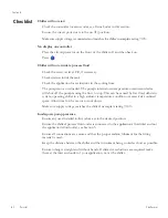
Page 44: ...e pump causing the flow to stop This can be caused by low fluid debris in system operating chiller in a high ambient temperature condition or excessively confined space Allow time for the motor to cool down Make sure supply voltage matches the chiller s nameplate rating 10 Inadequate pump pressure Ensure any user installed in line valves are in the desired position Ensure the chiller s process flu...

Page 45: ...es with the site requirements in Section 3 Make sure supply voltage matches chiller nameplate rating 10 If the temperature continues to rise make sure your application s heat load does not exceed the rated specifications Check for high thermal gradients e g the application load is being turned on and off or rapidly changing Some installations require PID value adjustment Contact us for instruction...

Page 46: ...econds The display will show the first two digits for example 3 Press The display will show the remaining digits to the left of the decimal for example 4 Press The display will show the decimal point and the digit to the right of the decimal point for example 5 Press The display will show the revision letter as its equivalent number for example A 6 Press Disregard this display 7 Press The display ...

Page 47: ...5 6 3 11 3 3 3803 7 502 5 6 7 2 3 25 1 6 5 9 12 6 7 7 7 33 615 5 75 0 7 5 6 20 352 7 7 7 7 7 6 1 250 7 21 6 21 17 1 6 6 26 72 28 21 21 7 21 7 7 12 857 5 6 2685 6 0 28 72 27 5 7 1 7 502 6 5 6 17 3 56211 7 287 5 77 1 87 25 7 21 520 7 502 6 5 6 17 3 25 1 1 1 3 25 1 7 502 7KHUPR LVKHU 6FLHQWLILF 1 0 5 x 1 1 721 1 5 5 72 127 6 6 7 21 25 72 5 1 9 8 6 3 0 0 ...

Page 48: ... models I II III All rated 1 100 Volts 50 Hz 100 Volts 60 Hz or 2 115 Volts 60 Hz or 3 220 Volts 60 Hz or 4 230 Volts 50 Hz Equipment Class Measurement control and laboratory Directives and Standards 2004 108 EC Electromagnetic Compatibility EMC Directive EN 61326 1 2006 Electrical equipment for measurement control and laboratory use EMC requirements EMC Class A 2006 95 EC Low Voltage Directive LV...

Reviews: