background image

Summary of Contents for UGAA

Page 1: ...atic Pressure Range 5 Cabinet and Duct Dimensions 6 Filter Sizes Upflow 8 Inlet Gas Pressure Range 9 High Altitude Conversion 1 Ratings Physical Electrical Data Upflow Models 11 Roof Pitch 14 Horizont...

Page 2: ...ain drywall dust is the key issue as that dust can be pulled into the circulating blower motor plugging the motor vents coating the rotors and stators etc which can lead to a potential fire hazard c T...

Page 3: ...area where the furnace is being exposed to the fol lowing substances and or chemicals Permanent wave solutions Chlorinated waxes and cleaners Chlorine based swimming pool chemicals Water softening che...

Page 4: ...r to circulate through the air conditioning and heating equipment Air must circulate to and from the conditioned space A CAUTION The cooling coil must be installed in the supply air duct down stream o...

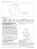
Page 5: ...0 035 20003 001 Rev B 1205 TABLE 3 External Static Pressure Range Input Output MBH kW MBH kW 75 22 0 60 17 6 75 22 0 60 17 6 100 29 3 80 23 4 Nominal Air Flow CFM cmm 1200 34 0 1600 45 3 1600 45 3 Ext...

Page 6: ...he furnace blower is rated The return air duct or plenum can be connected to the furnace by performing the following steps 1 Bend the 3 4 1 905 cm flanges that will be used to attach the return air pl...

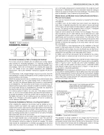
Page 7: ...obile Home and Modular Home Upflow Horizontal Return Plenum Connections The return air duct and the return air plenum is required by the furnace manufacturer If a upflow return air duct system and ret...

Page 8: ...ottom Remove the corresponding cabinet cut outs per instruc tions provided 2 Install the external filter box to the side of the cabinet and secure to the cabinet as specified in the instructions provi...

Page 9: ...pressures required for safe fur nace operation The minimum inlet gas pressure required to obtain the BTU input specified on the rating plate and in these instructions is shown below 4 5 W C 1 12 kPA f...

Page 10: ...re 11 5 Remove and discard natural gas orifices 6 Remove LP Propane orifices from the bag attached to the gas valve 7 Install the LP Propane gas orifices supplied with the furnace Tighten to 15 25 inc...

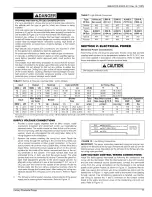
Page 11: ...way 10x8 25 4 x 20 3 6 7 15 14 10x 0 25 4 x 25 4 8 5 15 14 10x 0 25 4 x 25 4 8 5 15 14 Wire size and over current protection must comply with the National Electrical Code NFPA 70 1atest edition and al...

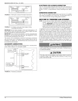
Page 12: ...terminals HUM and HUM N for humidifier connections are located on the control board The terminals provide 115 VAC 1 0 amp maximum during heating system operation SECTION Vh TWINNING AND STAGING NOTE...

Page 13: ...SI Z223 1 latest edition and or all local code or utility requirements 66840 035 20003 001 Rev B 1205 TWINNING Single Wire Twinning The control in the furnace has the single wire twinning feature With...

Page 14: ...eventing the possibility of any safety devices being bypassed Single Wire Staging Operation Heating On a call for first stage heat W1 signal from the wall thermo stat Furnace 1 wilI start the ignition...

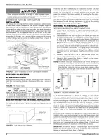
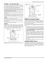
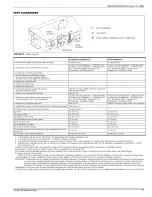
Page 15: ...035 20003 001 Rev B 1205 CH IMNEY OR GAS VENT VENTILATION LOUVERS each end of attic OUTLET AIR INLET AIR DUCT ends 1 ft 30 cm above floor FIGURE 22 Air Inlet Outlet and Chimney Connections VENTING INT...

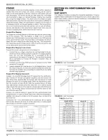
Page 16: ...to the termination securing the pipe connections with screws CHIMNEY OR GAS VENT OPENING OPENING FIGURE 25 Typical Chimney Connections FIGURE 26 Horizontal Air Inlet Outlet and Chimney Connections VE...

Page 17: ...t to the building 10 ft 304 8 cm 10 ft 3048 cm The vent shall extend above the highest point where it passes through the roof 18 48 cm 18 46 cm not less than Any obstruction within a horizontal distan...

Page 18: ...evels of CARBON MONOX IDE which can lead to serious injury property damage and or death An unconfined space is not Iess than 50 cu ft 1 42 m3 per 1 000 Btu hr 0 2928 kW input rating for all of the app...

Page 19: ...onfined space The duct shall be least the same cross sectional area as the free area of the air supply inlet opening to which it connects The blocking effects of louvers grilles and screens must be gi...

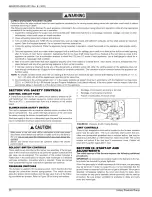
Page 20: ...ct the 24 volt transformer from overload caused by control circuit wiring errors This is an ATO 3 automotive type fuse and is located on the control board BLOWER DOOR SAFETY SWITCH This unit is equipp...

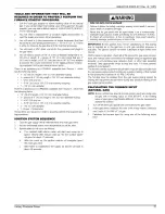
Page 21: ...aft blower motor will start and come up to speed Shortly after inducer start up the hot surface igniter will glow for about 17 seconds b After this warm up the ignition module will energize open the m...

Page 22: ...J m 3 x 2 cu ft x Cony x 0960 x 3600 MJ H Seconds it took to measure the 2 cu ft of gas NATURAL GAS INPUT CALCULATION EXAMPLE 392 x 2 x 0 960 x 3600 8476 90 5 Natural Gas BTU SCF 1030 39 2 MJ m 3 PROP...

Page 23: ...turned in clockwise manifold pressure is increased If screw is turned out counterclockwise mani fold pressure will decrease 8 After the manifold pressure has been adjusted re calculate the furnace in...

Page 24: ...Pa inwc kPa inwc kPa I 0 750 0 21 24 230 0 0038 li _ 0 01 0 0025 i_lil_ 0 01 0 0025 i_Ii1_i_015 0 0374 751 1000 21 27 28 32 330 0 0054 0 05 0 0125 0 05 0 0125 0 2 0 0498 1001 1250 28 35 35 40 330 0 00...

Page 25: ...8 6 1590 45 0 1462 41 4 1312 37 2 100 80 293 234 2 C Medium 1667 47 2 1696 48 0 1656 46 9 1597 45 2 1523 43 1 1438 40 7 1330 37 7 1191 33 7 Low 1130 32 0 1145 32 4 1177 33 3 1194 33 8 1181 33 4 1146 3...

Page 26: ...S I E UOAA UDA _ RO_5 _C Li OUT SWI C H S _4 RiGHt FG8 GDC n 8_T S OE LJ_AA UGA_ lr_s Fbg i_P PR_StlAF S_ TCH _dRNER _DX VENTOn TRANSFORMEA _0 _ OEN I_I O r_UN _ W _ C I OR Z_V CONN C ION _O0_d n_Er_...

Page 27: ...NOTES 66840 035 20003 001 Rev B 1205 Unitary Products Group 27...

Page 28: ...ge without notice Printed in U S A Copyright st by York International Corp 2005 All rights reserved Unitary Product Group 5OO5 York Drive 66840 035 20003 001 Rev B 1205 Supersedes 035 20003 001 Rev A...

Reviews: