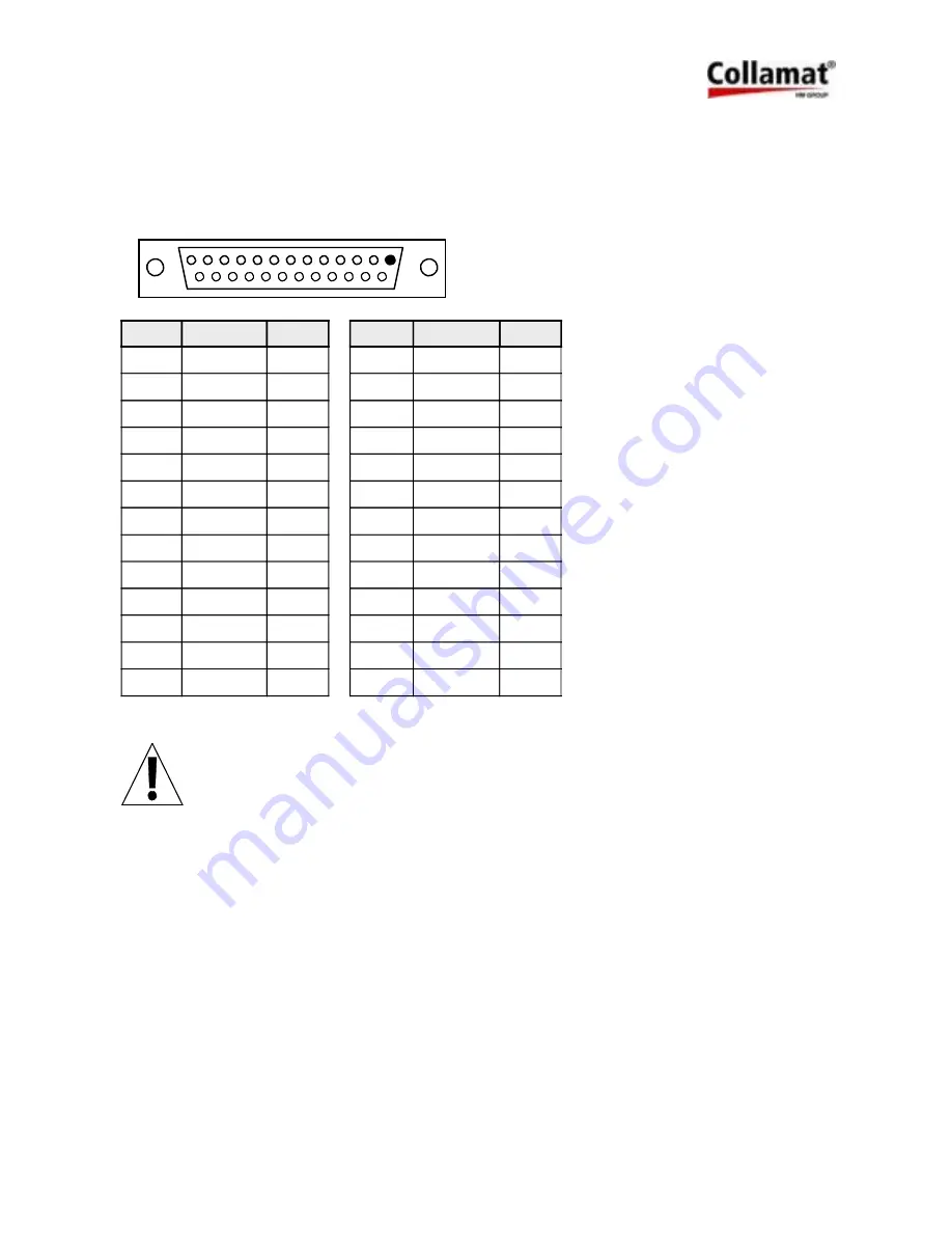
7.5 Connector layouts of the monitor C8600
7.5.1 Connector X3, DISPENSER
To this connector the controlcable to the traction unit is attached. The signals of this connector
are used especially to control the dispenser and its units.
Pin
Name
In/Out
Pin
Name
In/Out
1
GND
14
+12V
2
GND
15
+12V
3
GSC2
I
16
CLOCK
O
4
LSC
I
17
FEED
O
5
TUNIT
I
18
TCY
O
6
READY
I
19
GND
7
GND
20
NSTPO
O
8
GND
21
GSC3-
I
9
LLO
I
22
GSC3+
I
10
GSC1
I
23
+12V
11
GND
24
NSTPI+
I
12
GND
25
NSTPI-
I
13
GND
Pin assignment of the connector DISPENSER
ATTENTION:
For the connection of the dispenser signals a shielded cable must be used.
The cable must not be placed near power electronic devices. See also
chapter Cabling.
D I S P E N S E R
14
25
13
1
5999.545-01G 28.02.2006 WM
Page 35 / 65
Summary of Contents for Etiprint Inline
Page 65: ...Etiprint Inline Manufacturer s declaration Register A Manufacturer s declaration...
Page 66: ...Etiprint Inline Manufacturer s declaration 66...
Page 68: ...Etiprint Inline Manufacturer s declaration 68...
Page 69: ...Etiprint Inline Replacement parts Wear parts Register B Replacement parts Wear parts...
Page 70: ...Etiprint Inline Replacement parts Wear parts 70...
Page 74: ...Etiprint Inline Replacement parts Wear parts 74 Draw mechanism spare parts cont...
Page 78: ...Etiprint Inline Electric circuit drawing with printer type SATO...
Page 79: ......
Page 80: ......
Page 82: ...Etiprint Inline Electric circuit drawing with printer type ZEBRA...
Page 84: ......
Page 86: ...Etiprint Inline Collamat 8600 9100 Monitor Operating instructions...
Page 87: ...Collamat 8600 9100 Operating instructions Monitor 5999 530 01F...
Page 144: ...Etiprint Inline Collamat 8600 9100 Monitor Technical Manual...
Page 145: ...Collamat 8600 Technical handbook 5999 545 01G...
Page 188: ......


