background image


SG Series Technical Manual


Page 2 of 10 


SG Series Scanners 


SG 36m, 36c & 36e 
SG 44m, 44c & 44e


Technical Manual 


Issue 1 


©Colortrac Ltd 2017 


The product and the contents of this publication may be changed without prior notification. 


Colortrac Ltd makes every effort to ensure this publication is free from error.  Misprints, errors 
or quality observations should be reported to Technical Support, Colortrac Ltd. 


Colortrac Ltd shall not be liable for any damages, errors, issues or events that result from the 
use of the equipment or this manual. 


No part of this product or publication may be reproduced, 
copied or transmitted in any form or by any means without 
permission from: 
 

Colortrac Ltd. 
Units 3 

– 5 Brunel Court. 

Burrel Road. 
St Ives, 
Huntingdon, 
Cambridgeshire, 
PE27 3LW. 
United Kingdom. 


Tel: +44 (0)1480 464618 

Fax: +44 (0)1480 464620 


www.colortrac.com


Summary of Contents for SmartLF SG 36e

Page 1: ...C Co ol lo or rt tr ra ac c S Sm ma ar rt tL LF F S SG G S Se er ri ie es s C Ca am me er ra a F Fo oc cu us s...

Page 2: ...errors or quality observations should be reported to Technical Support Colortrac Ltd Colortrac Ltd shall not be liable for any damages errors issues or events that result from the use of the equipment...

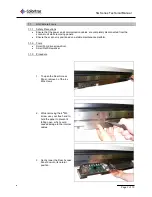
Page 3: ...he scanner is positioned on a stable maintenance platform 1 1 2 Tools Small Pozi drive screwdriver Small Flat Screwdriver 1 1 3 Procedure 1 To open the Rear Access Panel remove 3 of the 4 x M3 screws...

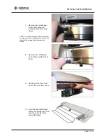
Page 4: ...ical Manual Page 4 of 10 4 Remove the 6 x M3 screws from the Rear Outer Cover 5 Open the Lid Assembly by depressing the Lid Latches at either end 6 Lift the Rear Outer Cover up and away from the rear...

Page 5: ...ising the screwdriver or using some form of sticky putty to hold the screw to the screwdriver to remove the screws 8 Remove the 2 x M3 lower screws from the Rear Inner Cover 9 Carefully lift the Rear...

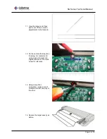
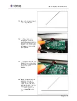
Page 6: ...make adjustments to that camera 12 On the camera that requires focusing it is recommend using a pencil to mark the original position of the focus screw for reference 13 Using a small flat screwdriver...

Page 7: ...to the reference mark and move a bit more in that same direction 17 If the image looks worse turn it back to the reference mark and continue to move a small amount in that same direction 18 Repeat un...

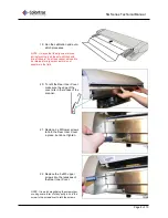
Page 8: ...ent as this is not possible in the field 20 To refit the Rear Inner Cover make sure the edge of the cover sits in the recess of the scanner 21 Replace 2 x M3 lower screws to hold the Rear Inner Cover...

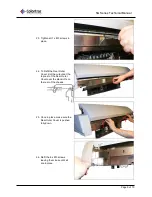
Page 9: ...e 24 To Refit the Rear Outer Cover slot the cutouts at the top rear of the Rear Outer Cover over the stand offs on the rear of the chassis 25 Once in place make sure the Rear Outer Cover is pushed ful...

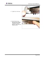
Page 10: ...hnical Manual Page 10 of 10 27 Tighten the 6 x M3 screws 28 Close the Rear Access Panel gently lift into postion making sure that no cables are trapped or damaged Refit the 4 x M3 screws while holding...

Reviews: