16
Capricorn II Plus User Manual
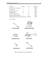
Refer to Figures 3 & 4 for key references. The following parts should be included in
the shipping carton:
Ref. Qty Description
-
(1) User Manual
1
(1) Cross Arm Support
2
(1) Wind Cup Hub Assembly (with spare top lock nut)
3
(1) Wind Direction Vane (with spare top screw)
-
(1) Console
-
(1) 25-foot cables attached to temperature sensors for console display
-
(1) 25-foot cable attached to humidity sensor assembly for console display
4
(1) 3-foot cable coil with connector half molded to a wind direction sensor body (4a)
(white, T-shaped, PVC fitting with two cables protruding) which in turn is con-
nected by a single cable to a wind speed sensor body (4b) (white, T-shaped,
PVC fitting).
-
(1) 50-foot wind sensor cable coil with connector half.
-
(1) Hardware Assembly Kit (see Fig. 4) consisting of:
5
(1) U-Bolt
5
(2) U-bolt nuts
5
(2) Locking washers
5
(2) U-bolt plates, one serrated, one rounded
6
(6) Black plastic tie wraps (UV-resistant)
7
(1) Top screw (for clamping the direction vane shaft to the vane holder)
8
(2) Stainless steel sheet metal screws (for mounting wind sensors to Cross
Arm Support)
9
(1) Internal locking star washer (for threaded shaft of wind direction sensor
10 (1) Top lock nut (to be placed on threaded shaft of wind speed sensor,
above wind cup assembly)
-
(1) Console power cord
11 (1) Wind Sensor Cable Connector


