background image

 16

SECTION 9:  ADJUSTMENTS

LEVELING THE DECK

WARNING: 

Cutting blades are sharp.

Always protect hands by wearing heavy
leather work gloves to grasp blades.

NOTE: 

Check the tractor’s tire pressure before 

performing any deck leveling adjustments. Refer to 
TIRES in the maintenance section of this manual for 
further information regarding tire pressure. 

Front to Rear

The front of the cutting deck is supported by a
stabilizer bar that can adjusted to level the deck from
front to rear. The front of the deck should be 1/4" to
3/8" lower than the rear of the deck. Adjust if
necessary as follows:

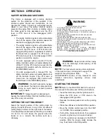
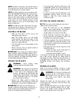
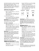
WARNING: 

Turn the tractor’s engine off,

remove the key from the ignition switch
and apply the tractor’s parking brake
before making any adjustments to the
deck.

• With the tractor parked on a firm, level

surface, place the lift lever in the top notch
(highest position) and rotate the blade nearest
the discharge chute so that it is parallel with
the tractor.

• Measure the distance from the front of the

blade tip to the ground and the rear of the
blade tip to the ground. The first measurement
taken should be between 1/4" and 3/8" less
than the second measurement. Determine the
approximate distance necessary for proper
adjustment and proceed, if necessary, to the
next step. 

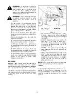
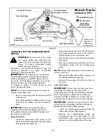
• Loosen the two jam nuts on the rear side of

the deck stabilizer bracket. See Figure 9A.

• Locate the two lock nuts on the opposite side

of the stabilizer bracket. See Figure 9A.
Tighten the lock nuts to raise the front of the
deck; loosen the lock nuts to lower the front of
the deck.

• Retighten the two jam nuts loosened earlier

when proper adjustment is achieved.

Side to Side 

If the cutting deck appears to be mowing unevenly, a side to side adjustment can be performed. Adjust if 
necessary as follows:

Figure 9  

• With the tractor parked on a firm, level

surface, place the deck lift lever in the top
notch (highest position) and rotate both blades
so that they are perpendicular with the tractor.

• Measure the distance from the outside of the

left blade tip to the ground and the distance

from the outside of the right blade tip to the
ground. Both measurements taken should be
equal. If they’re not, proceed to the next step.

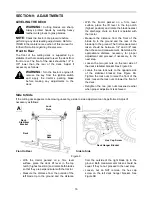
• Loosen, but do NOT remove, the hex cap

screw on the left deck hanger bracket. See
Figure 9B.

Jam 

Deck

Stabilizer

Bracket

Nuts

Lock 

Nuts

Deck

Hex Cap Screw

Deck Hanger Bracket

A

B

Front to Rear

Side to Side

Summary of Contents for 0606G

Page 1: ...OPERATOR S MANUAL IMPORTANT READ PRINTED IN THE U S A 772C0642A 02 03 AutoDrive Lawn Tractor Models 0606G SAFETY RULES AND INSTRUCTIONS CAREFULLY 6606G 6606H ...

Page 2: ...as a model plate You can locate it by lifting the seat and looking at the seat bracket An example of what the model plate will look like is shown below SECTION 3 CALLING CUSTOMER SUPPORT LOCATE YOUR MODEL NUMBER AND SERIAL NUMBER Record this information in the space provided To find your unit s specific model number and serial number see SECTION 2 FINDING YOUR MODEL NUMBER If you are having diffic...

Page 3: ...tact or thrown object injuries 13 Stop the blade s when crossing gravel drives walks or roads and while not cutting grass 14 Watch for traffic when operating near or crossing roadways This machine is not intended for use on any public roadway 15 Do not operate the machine while under the influence of alcohol or drugs 16 Mow only in daylight or good artificial light 17 Never carry passengers 18 Dis...

Page 4: ...ock your vision of a child who may run into the machine f Disengage the cutting blade s before shifting in reverse The No Cut In Reverse feature is a reminder not to cut in reverse and to help avoid back over accidents Do not defeat it g Keep children away from hot or running engines They can suffer burns from a hot muffler h Remove key when machine is unattended to prevent unauthorized operation ...

Page 5: ...tra caution when servicing them 7 Never tamper with the safety interlock system or other safety devices Check their proper operation regularly 8 After striking a foreign object stop the engine disconnect the spark plug wire s and ground against the engine Thoroughly inspect the machine for any damage Repair the damage before starting and operating 9 Never attempt to make adjustments or repairs to ...

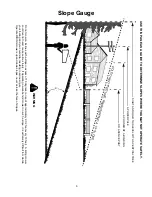
Page 6: ...OPES WHERE YOU MAY NOT OPERATE SAFELY Do not mow on inclines with a slope in excess of 15 degrees a rise of approximately 2 1 2 feet every 10 feet A riding mower could overturn and cause serious injury If operating a walk behind mower on such a slope it is extremely difficult to maintain your footing and you could slip resulting in serious injury Operate RIDING mowers up and down slopes never acro...

Page 7: ... engine performance and could cause permanent engine damage The gasoline tank is located under the hood and has a capacity of approximately two gallons Do not overfill WARNING Gasoline produces noxious fumes Never fill fuel tank indoors Always fill the fuel tank in a well ventilated area to avoid inhalation of gasoline fumes WARNING Never smoke while fueling your tractor or fill the fuel tank whil...

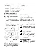
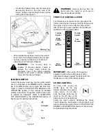
Page 8: ...ual for detailed instructions Figure 4 WARNING Remove the key from the tractor when the tractor is not in use to prevent accidental starting THROTTLE CONTROL LEVER The throttle lever is located on the right side of the tractor s dash panel This lever controls the speed of the engine and on some units the choke control also When set in a given position the throttle will maintain a uniform engine sp...

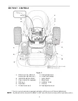
Page 9: ...edal D Shift Lever K AutoDrive Pedal E Cup Holder L Lift Lever F Throttle Control Lever M Seat Adjustment Lever I F B C H G E L K J M P 1 10 P A D NOTE Steering Wheel not shown for clarity NOTE Style varies by model A NOTE Any reference in this manual to the RIGHT or LEFT side of the tractor is observed from operator s position Tractors vary by model and are equipped with either a PTO lever or a P...

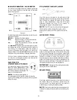
Page 10: ...s the seat PTO POWER TAKE OFF LEVER The PTO lever is located on the left side of the dashboard next to the steering wheel Move the PTO lever forward to engage the power to the cutting deck or other attachments move the PTO lever backward toward the rear of the tractor to disengage the power to the attachments NOTE The PTO lever must be in the disengaged OFF position when starting the engine when s...

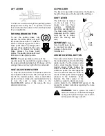
Page 11: ...of this manual for more detailed instructions CUP HOLDER The tractor s cup holder is located on the fender to the left of the seat just to the rear of the shift lever SHIFT LEVER The shift lever is located on the left side of the fender and has three positions FORWARD NEUTRAL and REVERSE The brake pedal must be depressed and the tractor must not be in motion when the moving shift lever IMPORTANT N...

Page 12: ... cutting height notches on the right side of the fender Then adjust the deck wheels so that they are at least 1 4 inch to 1 2 inch above the ground when the tractor is on a smooth flat surface such as a driveway WARNING Keep hands and feet away from the discharge chute opening of the cutting deck NOTE The deck wheels are an anti scalp feature of the deck and are not designed to support the weight ...

Page 13: ...tion of travel when the tractor is in motion Always use the brake pedal to bring the tractor to a complete stop before shifting To move forward place the shift lever in the FORWARD position then slowly depress the AutoDrive pedal until the desired speed is achieved To move in reverse place the shift lever in the REVERSE position check that the area behind is clear then slowly depress the AutoDrive...

Page 14: ... ELECTRIC PTO POWER TAKE OFF KNOB if so equipped Move the throttle control lever to the FAST rabbit position Pull the PTO knob outward into the engaged ON position See Figure 7 Keep the throttle lever in the FAST rabbit position for the most efficient use of the cutting deck and other attachments The operator must remain in the tractor seat at all times If the operator should leave the seat withou...

Page 15: ...NG AutoDrive lawn tractors come equipped with a mulch kit which incorporates special blades already standard on your tractor in a process of recirculating grass clippings repeatedly beneath the cutting deck The ultra fine clippings are then forced back into the lawn where they act as a natural fertilizer Observe the following points for the best results when mulching Figure 8 Never attempt to mulc...

Page 16: ...ld be between 1 4 and 3 8 less than the second measurement Determine the approximate distance necessary for proper adjustment and proceed if necessary to the next step Loosen the two jam nuts on the rear side of the deck stabilizer bracket See Figure 9A Locate the two lock nuts on the opposite side of the stabilizer bracket See Figure 9A Tighten the lock nuts to raise the front of the deck loosen ...

Page 17: ...er in one direction than the other or if the ball joints are being replaced due to damage or wear the steering drag links may need to be adjusted Figure 11 Adjust the drag links so that equal lengths are threaded into the ball joint on the left side and the ball joint on the right side Loosen the jam nut found on the drag link at the rear of the ball joint See Figure 11 Remove the hex nut and lock...

Page 18: ...oil drain valve to expose the oil drain port See Figure 13 Push oil drain hose packed with unit onto the oil drain port Route the opposite end of the hose into an appropriate oil collection container with a capacity great enough to collect the used oil Push the oil drain valve in slightly then rotate counterclockwise and pull outward to begin draining oil See Figure 13 Service the oil filter if so...

Page 19: ...in the operator s position with the cutting deck engaged for a minimum of two minutes allowing the underside of the cutting deck to throughly rinse Disengage the tractor s PTO Turn the ignition key to the STOP position to turn the tractor s engine off Turn the water off and detach the hose coupler from the water port on your decks surface Repeat step 4 11 on the opposite side of the cutting deck C...

Page 20: ...eck Removal then gently flip the deck over to expose its underside Place a block of wood between the center deck housing baffle and the cutting blade to act as a stabilizer See Figure 17 Use a 15 16 wrench to remove the hex flange nut that secures the blade to the spindle assembly See Figure 16 Figure 16 Figure 17 To properly sharpen the cutting blades remove equal amounts of metal from both ends ...

Page 21: ... your tractor are subject to wear and should be replaced if any signs of wear are present IMPORTANT The V belts found on your tractor are specially designed to engage and disengage safely A substitute non OEM V belt can be dangerous by not disengaging completely For a proper working machine use factory approved belts To change or replace the deck belt and PTO belt on your tractor proceed as follow...

Page 22: ...ard the rear of the tractor to release tension on the upper drive belt Remove the belt from around the transmission idler pulley Remove the upper drive belt from around the transmission pulley and the variable speed pulley NOTE Slowly rotate the pulley counterclockwise to roll the belt off of it Remove the upper drive belt by pulling it up through the battery tray opening Reroute the new upper dri...

Page 23: ...ers EXACTLY as the old one was routed Refer to Figure 21 The AutoDrive pedal is properly adjusted when the hole found in the double idler bracket has approximately 1 3 8 of travel with ten pounds of pressure applied to the AutoDrive pedal See Figure 22 Figure 22 Adjust the AutoDrive pedal after replacing the drive belts on your tractor if necessary as follows Locate the speed control assembly on t...

Page 24: ...ime charge the battery with an automotive type 12 volt charger for a minimum of one hour at six amps WARNING Batteries give off an explosive gas during and for some time after charging Charge battery in a well ventilated area and do not allow a spark or an open flame near the battery SECTION 11 LUBRICATION WARNING Always stop the engine and disconnect the spark plug wire s and ground against the e...

Page 25: ...n body panels burned by the exhaust pipe or muffler or rubbed against a moving part Engine cranks but will not start Throttle or choke not in starting position No fuel to the carburetor No spark to spark plug s Dirty aircleaner Refer to the OPERATION section of this manual for the correct position of the throttle control and choke for starting Gasoline tank empty Fill Fuel line or in line fuel fil...

Page 26: ...ers are considered consumable items and as such are not warranted NOTE Regular maintenance replacement parts and related inspections and adjustments are excluded from coverage when made as part of normal maintenance service TRACTOR ATTACHMENT WARRANTY Mower decks included with your product or sold separately as an attachment for your garden tractors will be warranted according to the above terms o...

Reviews: