background image

17

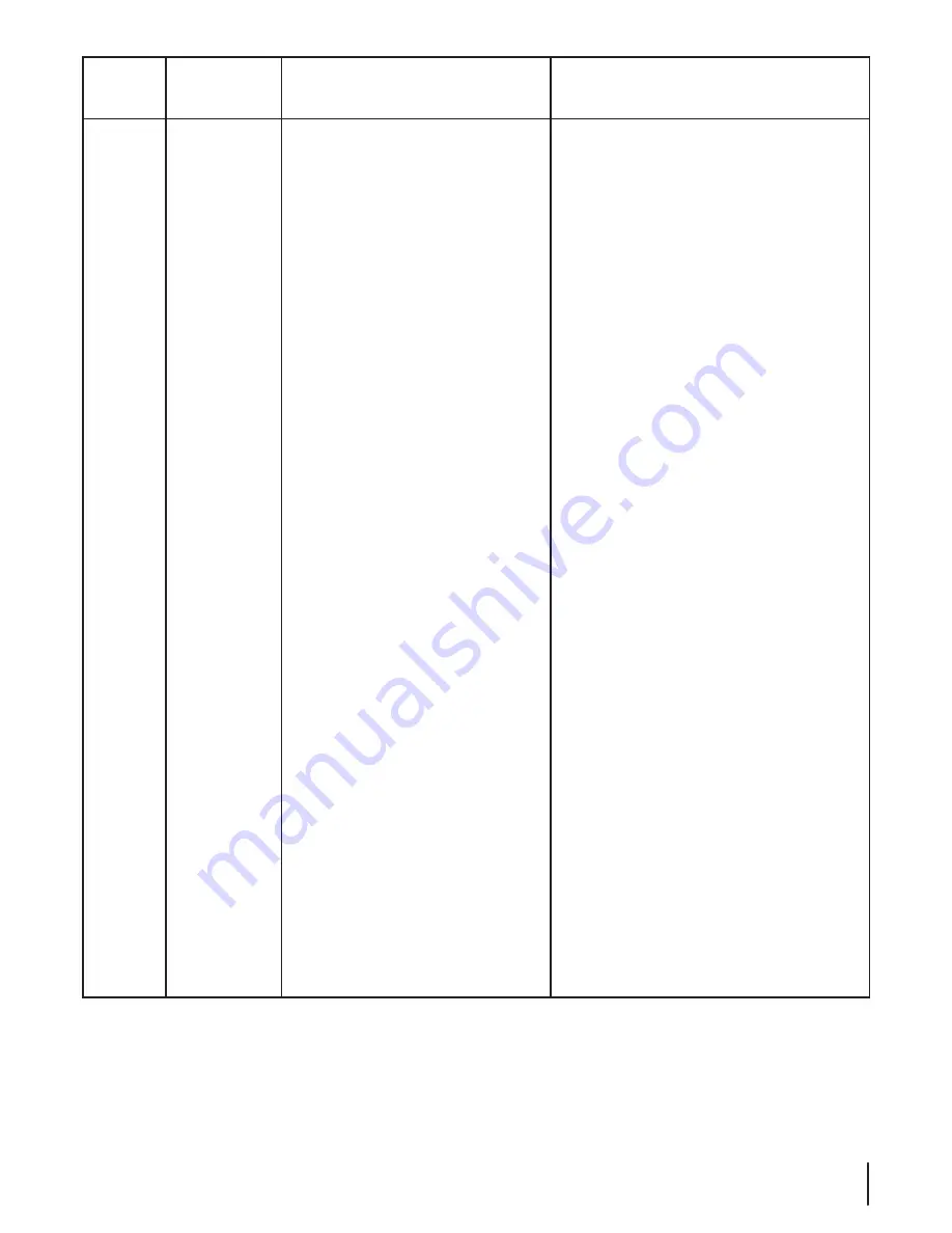
25A-262J

10.29.14

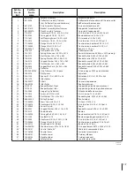
Ref. No.

No. de

Réf. 

Part No.

No. de

pièce

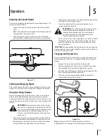
Description

Description

1

618-07086

Spindle Assembly

Ensemble de fusée

2

631-0096

Deflector Assembly, Trimmer

Déflecteur de la tondeuse à fil (Comprend les

(incl. Deflector Flap and Hardware)

déflecteur et boulonnerie)

3

681-0159

Axle Assembly, Trimmer

Essieu de la tondeuse à fil

4

681-0181A

Bracket Assembly, Idler Trimmer

Support de la tondeuse à fil

5

681-05007A

Deck Assembly, Trimmer

Corps de la tondeude à fil

6

710-0237

Hex Screw 5/16-24, .625, Gr. 5, Std

Vis à tête hex. 5/16-24 x 0,625 Qual. 5

7

710-0703

Carriage Bolt 1/4-20, .75, Gr. 5

Boulon ordinaire 1/4-20 x 0,75

8

710-1652

Self-Tapping Screw 1/4-20 x .625

Vis taraudée 1/4-20 x 0.625

9

710-3015

Hex Screw, 1/4-20, .75, Gr. 5, Std

Vis à tête hex. 1/4-20 x 0,75 Qual. 5

10

712-04063

Flange L-Nut 5/16-18, Gr. F

Contre-écrou à embase 5/16-18, Gr. F

11

712-04064

Flange L-Nut 1/4-20, Gr. F

Contre-écrou à embase 1/4-20, Gr. F

12

734-04030

Wheel 14 x 1.75, Gray

Roue 14 x 1,75, gris

13

731-2329

Trailshield 5.85 x 14.50

Déflecteur arrière

14

732-1022

Spring, Extension, .50 OD x 3.375

Ressort d’extension 0,50 dia. x 3,375 po de lg.

15

736-0173

Flat Washer .280 x .740 x .063

Rondelle plate 0,280 x 0,740 x 0,063

16

736-0182

Spring Washer .500 x 1.00 x .022

Rondelle ressort 0,50 x 1,0 x 0,022

17

736-0270

Cupped Washer .265 x .750 x .060

Rondelle creuse 0,265 x 0,75 x 0,060

18

736-0371

Flat Washer .343 x .880 x .062

Rondelle plate 0,343 x 0,880 x 0,062

19

736-0425

Cupper Washer .325 x .930 x .045

Rondelle creuse 0,325 x 0,930 x 0,045

20

731-2315

Deflector

Déflecteur

21

490-040-M035

Line, Trimmer .155, 10-pack

Fil de coupe de 0,155 po de diamètre

22

748-0278

P/M Spacer

Entretoise

23

750-1240

Spacer .51 ID x 1.00 OD x .38

Entretoise 0,51 ID x 1,00 OD x 0,38

24

750-1275

Idler Spacer

Entretoise

25

754-05077

V-Belt

Courroie trapézoïdale

26

756-05108

Idler Pulley

Poulie de tension

27

781-1020

Keeper Bracket, Front

Support du guide de courroie avant

28

781-1028

Keeper Bracket, Idler

Support du guide de la poulie de tension

29

782-9065

Hinge Clip, Trailshield

Attache du déflecteur arrière

30

710-1823

Screw, HL #12-16 x .625

Vis H-Low no. 12-16 x 0.625

31

736-0400

Flat Washer .194 x .62 x .063

Rondelle plate  0,194 x 0,62 x 0,063

32

656-05000

Pulley/Flywheel

Poulie/volant

33

710-0654A

Sems Screw 3/8-16 x 1.0

Vis Sems 3/8-16 x 1,0

34

710-06074

Hex Screw 3/8-24 x 1.25 Gr8

Vis à tête hex. 3/8-24 x 1,25 Qual. 5

35

731-09688

Cover, Shroud

Capot

36

736-0452

Cupped Washer .396 x 1.14 x .095

Rondelle creuse 0,396 x 1,14 x 0,095

37

720-0279

Knob, Handle

Bouton

38

710-04998

Carriage Bolt 5/16-18, 1.00 Gr. 5

Boulon ordinaire 5/16-18 x 1,0 Qual. 5

39

710-1205

Eye Bolt 1/4-20

Boulon de guidage de cordon 1/4-20

40

710-3005

Hex Screw 3/8-16 x 1.25 Gr. 5, Std

Vis à tête hex. 3/8-16 x 1,25 Qual. 5

41

712-04065

Flange L-Nut 3/8-16, Gr. F

Contre-écrou à embase 3/8-16 Qual. F

42

720-04122

Wing Knob 5/16-18 Black

Bouton 5/16-18 Noir

43

738-04419A

Shoulder Screw .375 x .148 x 1/4-20

Vis à épaulement 0,375 x 0,148 x 1/4-20

44

746-05141

Control Cable, 48”

Câble de la commande, 48 po

45

747-06246

Control Lever

Levier de la commande

46

749-05102

Handle, Lower

Guidon, inférieur

47

749-05103

Handle, Upper

Guidon, supérieur

 —

723-0400

Safety Glasses

Lunettes de sécurité

Summary of Contents for 260 series

Page 1: ... INSTRUCTIONS IN THIS MANUAL BEFORE ATTEMPTING TO OPERATE THIS MACHINE FAILURE TO COMPLY WITH THESE INSTRUCTIONS MAY RESULT IN PERSONAL INJURY OPERATOR S MANUAL LES DISTRIBUTIONS RVI LTÉE 10655 BOUL HENRI BOURASSA OUEST ST LAURENT Qc H4S 1A1 MTD LLC P O BOX 361131 CLEVELAND OHIO 44136 0019 769 10351 10 29 15 String Trimmer Mower Model Series 260 ...

Page 2: ...ual frequently to familiarize yourself with the machine its features and operation Please be aware that this Operator s Manual may cover a range of product specifications for various models Characteristics and features discussed and or illustrated in this manual may not be applicable to all models The manufacturer reserves the right to change product specifications designs and equipment without no...

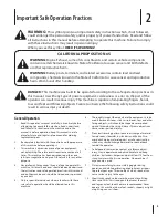
Page 3: ...injury stay in operator zone behind handles and keep children bystanders helpers and pets at least 75 feet from string trimmer while it is in operation Stop machine if anyone enters area 9 Always wear safety glasses or safety goggles during operation and while performing an adjustment or repair to protect your eyes Thrown objects which ricochet can cause serious injury to the eyes 10 Wear sturdy r...

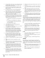
Page 4: ... of the body in the trimmer line area until you are sure the spindle has stopped rotating 23 Never operate string trimmer without proper trail shield discharge cover control lever or other safety protective devices in place and working Never operate string trimmer with damaged safety devices Failure to do so can result in personal injury 24 Muffler and engine become hot and can cause a burn Do not...

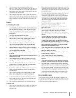
Page 5: ...er run an engine indoors or in a poorly ventilated area Engine exhaust contains carbon monoxide an odorless and deadly gas 2 Before cleaning repairing or inspecting make certain the spindle and all moving parts have stopped Disconnect the spark plug wire and ground against the engine to prevent unintended starting 3 Check the spindle and engine mounting bolts at frequent intervals for proper tight...

Page 6: ...ndary Air Injection SAI and Three Way Catalyst TWC if so equipped Spark Arrestor WARNING This machine is equipped with an internal combustion engine and should not be used on or near any unimproved forest covered brush covered or grass covered land unless the engine s exhaust system is equipped with a spark arrestor meeting applicable local or state laws if any If a spark arrestor is used it shoul...

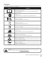
Page 7: ...EYE PROTECTION Always wear safety glasses or safety goggles when operating this machine DANGER BYSTANDERS Do not trim when children or others are around DANGER HAND FOOT CUT Keep hands and feet away from rotating parts DANGER THROWN DEBRIS Remove objects that can be thrown by the machine in any direction Wear safety glasses DANGER SLOPES Use extra caution on slopes Do not trim on slopes greater th...

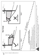
Page 8: ...ect See Figure 1 and Figure 2 4 Adjust gauge up or down until the left corner touches the slope See Figure 1 and Figure 2 5 If there is a gap below the gauge the slope is too steep for safe operation See Figure 2 above 1 5 d a s h e d l i n e Slope Gauge Figure 2 Figure 1 15 Slope 15 Slope WARNING Slopes are a major factor related to tip over and roll over accidents which can result in severe inju...

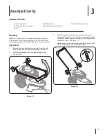
Page 9: ...rating your machine Upper Handle 1 Remove the wing knob and carriage bolt from the left lower handle and the right lower handle See Figure 3 1 2 Pivot the upper handle into the operating position See Figure 3 1 Figure 3 1 3 Move the upper handle into one of three positions by pivoting it forward or rearward Secure the upper handle to the lower handle using the carriage bolts and wing knobs removed...

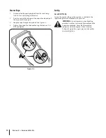
Page 10: ...ve Never fuel the machine indoors or while the engine is hot or running Extinguish cigarettes cigars pipes and any other sources of ignition Starter Rope 1 Disconnected the spark plug boot from the spark plug refer to the seperate Engine Manual 2 Pivot the control handle against the upper handle and pull the rope out of the engine 3 Loop the rope through the eye bolt See Figure 3 3 4 Tighten the e...

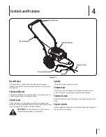
Page 11: ...eleasing the control lever stops the engine and trimmer spindle assembly WARNING This control lever is a safety device Never attempt to bypass its operations Spindle The spindle rotates the trimmer line Trimmer Line The trimmer line is attached to the spindle assembly and it is used to trim grass vegetation undergrowth and weeds Flywheel Screen Keep the flywheel screen free of grass clippings and ...

Page 12: ...right side without having to make any adjustments to the machine Operate the string trimmer at a slower walking speed when trimming tall thick weeds or grass Clean the underside of the trimmer after each use to remove any debris build up WARNING Shut the engine off and wait until the trimmer head comes to a complete stop before cleaning the discharge area The trimmer head continues to rotate for a...

Page 13: ...nto the upper part of the engine causing a starting problem 3 Scrape and clean the underside of the machine with a suitable tool Do not spray with water IMPORTANT Do not use a pressure washer or garden hose to clean the machine These may cause damage to the engine The use of water will result in shortened life and reduce serviceability 4 Put the trimmer back on its wheels on the ground If you had ...

Page 14: ...n gas cap plugged 4 Water or dirt in fuel system 5 Dirty air cleaner 6 Unit running with CHOKE if equipped applied 1 Connect and tighten spark plug boot 2 Clean fuel line fill tank with clean fresh gasoline 3 Clear vent 4 Drain fuel tank Refill with fresh fuel 5 Refer to engine manual 6 Push CHOKE knob in Engine overheats 1 Engine oil level low 2 Air flow restricted 1 Fill crankcase with proper oi...

Page 15: ...Notes 15 ...
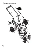
Page 16: ...Model Series Séries de modèles 260 44 37 47 46 34 15 20 25 27 1 11 10 28 26 36 32 43 40 2 30 31 14 4 24 22 18 10 15 10 11 42 39 41 46 29 38 11 8 13 40 45 5 19 6 16 23 16 17 33 3 17 9 35 12 12 41 7 21 10 9 ...

Page 17: ... 0 045 20 731 2315 Deflector Déflecteur 21 490 040 M035 Line Trimmer 155 10 pack Fil de coupe de 0 155 po de diamètre 22 748 0278 P M Spacer Entretoise 23 750 1240 Spacer 51 ID x 1 00 OD x 38 Entretoise 0 51 ID x 1 00 OD x 0 38 24 750 1275 Idler Spacer Entretoise 25 754 05077 V Belt Courroie trapézoïdale 26 756 05108 Idler Pulley Poulie de tension 27 781 1020 Keeper Bracket Front Support du guide ...

Page 18: ...rranty does not provide coverage in the following cases a The engine or component parts thereof These items may carry a separate manufacturer s warranty Refer to applicable manufacturer s warranty for terms and conditions The Powermore engine is not excluded under this agreement b Log splitter pumps valves and cylinders have a separate one year warranty c Routine maintenance items such as lubrican...

Page 19: ...E RESPECTIVE MANUFACTURERS SERVICE DEALERS Belts light bulbs clutch parts friction wheels grass bags tires seats rider deck wheels and cutting blades are covered by a 60 day limited warranty Batteries are warranted against defect for 90 days at 100 of their value and 50 of their value for the period between the 91st day and the 120th day Fuses shear bolts and blade adapters are considered consumab...

Reviews: