background image

6

3

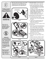
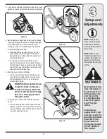
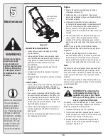
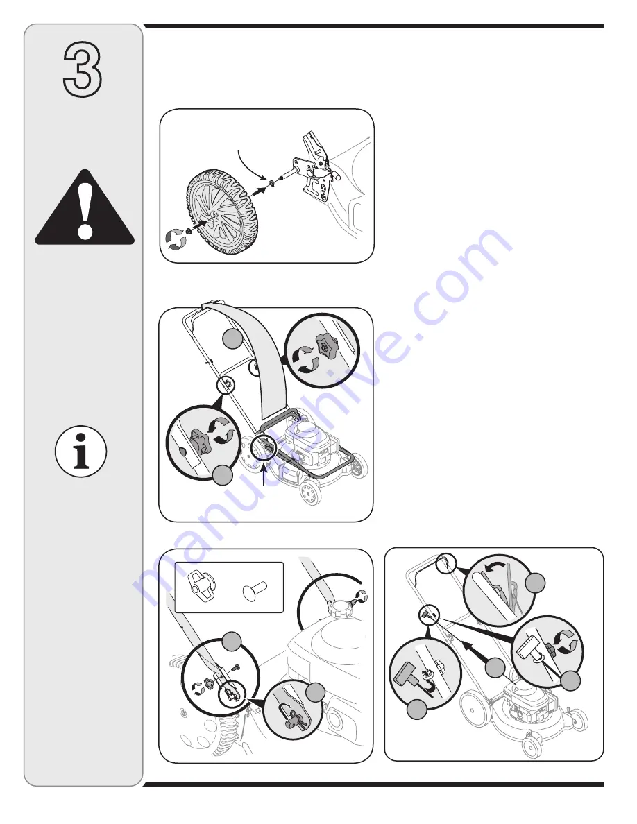
Figure 2

Figure 3

Figure 4

1.  Attaching Rear Wheels 

(If Not Already Attached)

a.  Place rear of the mower deck on raised blocks.
b.  Remove the hex flanged nut on the rear axle 

from each side and place the rear wheel on the 
axle. (On select models, these may be included 

separately in a plastic bag).

c. 

On models with 2” wide rear wheels

, make sure 

the spring washer is on the inside of the wheel 
between the wheel and the lawnmower, cupped 
side towards the bracket. See Figure 1.

d.  Reinsert the flanged nut into

 the axle as shown, 

and tighten securely. Repeat on other side.

2.  Remove loose parts and any packing material which 

may be between upper and lower handles. 
a.  Pull up and back on the upper handle to raise the 

handle from position A into the operating position. 
See Figure 2.

b.  Tighten knobs securing upper handle to lower 

handle. Make sure that each carriage bolt is 
seated properly in the handle.

3.  Locate hairpin clip in one hole on the weld pin on each 

side of lower handle.
a.  Remove hairpin clip from this hole. Using a pair of 

pliers, insert hairpin clip into the other hole on the 
weld pin. Repeat on other side. See Figure 3.

b.  Place one carriage bolt (found in the hardware 

pack included with your unit) in the upper hole of 
the right handle mounting bracket from the inside 
outward. See Figure 3. Secure with one wing nut. 
Repeat process on the left side.

4.  Rope guide Setup as follows, see Figure 4:

a.  Hold the blade control against the upper handle. 

Position A.

b.  Slowly pull starter rope out of engine. Position B.
c.  Slip starter rope into the rope guide. Position C.
d.  Tighten rope guide wing nut (star knobs).Position D.

Figure 1

Disconnect and 

ground the spark 

plug wire as instruct-

ed in the separate 

engine manual.

IMPORTANT

This unit is shipped 
WITHOUT GASOLINE 
or OIL.  After assem-
bly, service engine 
with gasoline and 
oil as instructed in 
the separate engine 
manual packed with 
your unit. 

Make sure to route 
cable outside the 
lower handle. Do not 
crimp cable while 
lifting the handle up.

Setup and 

Adjustments

WARNING

On models with 2” 

wide rear wheels only.

Handle Bracket

B

A

A

B

A

C

D

B

NOTE: 

This owner’s manual covers various models 

of lawnmowers. The units illustrated may vary 
slightly from your unit. Follow only those instruc-
tions which pertain to your model lawnmower.

Summary of Contents for 540 Series

Page 1: ...INSTRUCTIONS CAREFULLY BEFORE OPERATING EQUIPMENT Safety Setup Adjustments Operation Maintenance Troubleshooting Parts Lists Warranty LES DISTRIBUTIONS RVI LIMITÉE 2955 JEAN BAPTISTE DESCHAMPS LACHINE QUEBEC H8T 1C5 21 Rotary Mower Model Series 540 11 26 07 769 02853A ...

Page 2: ...4 Set Up Adjustments 6 Operation 8 Maintenance Off Season Storage 10 Trouble Shooting 12 Warranty 13 Illustrated Parts Lists 14 Customer Support 1 If you have difficulty assembling this product or have any questions regarding the controls operation or maintenance of this unit please call an authorized dealer Please have your unit s model number and serial number ready when you call See previous se...

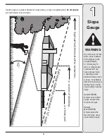
Page 3: ... and you could slip resulting in serious injury Operate RIDING mowers up and down slopes never across the face of slopes Operate WALK BEHIND mowers across the face of slopes never up and down slopes Sight and hold this level with a vertical tree or a corner of a building or a fence post F o l d a l o n g d o t t e d l i n e r e p r e s e n t s a 1 5 s l o p e 15 Use this page as a guide to determi...

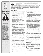
Page 4: ...nd automatically return to the disengaged position when released 18 Never operate the mower in wet grass Always be sure of your footing A slip and fall can cause serious personal injury If you feel you are losing your footing release the blade control handle immediately and the blade will stop rotating within three seconds 19 Mow only in daylight or in good artificial light Walk never run 20 Stop ...

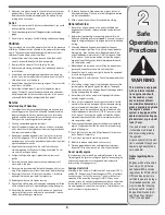
Page 5: ...odorless and deadly gas 2 Before cleaning repairing or inspecting make certain the blade and all moving parts have stopped Disconnect the spark plug wire and ground against the engine to prevent unintended starting 3 Check the blade and engine mounting bolts at frequent intervals for proper tightness Also visually inspect blade for damage e g bent cracked worn Replace blade with the original equip...

Page 6: ...insert hairpin clip into the other hole on the weld pin Repeat on other side See Figure 3 b Place one carriage bolt found in the hardware pack included with your unit in the upper hole of the right handle mounting bracket from the inside outward See Figure 3 Secure with one wing nut Repeat process on the left side 4 Rope guide Setup as follows see Figure 4 a Hold the blade control against the uppe...

Page 7: ...her on the pivot rod Let go of discharge door so that it rests on the grass catcher See Figure 8 WARNING Never operate mower unless the hooks on the grass catcher are firmly seated on the pivot rod and the rear discharge door rests firmly against top of the grass catcher 9 To remove grass catcher and utilize the mulching feature a Lift rear discharge door on the mower as shown in Figure 8 Lift gra...

Page 8: ...over the end of the spark plug wire make certain the metal loop on the end of the spark plug wire inside the rubber boot is fastened securely over the metal tip on the spark plug To Start Engine 1 If your unit is equipped with a primer prime engine as instructed in the separate engine manual packed with your unit 2 Standing behind the unit depress the blade control handle and hold it against the u...

Page 9: ...hor oughly inspect the mower for any damage and repair the damage before restarting and operating the mower Extensive vibration of the mower during operation is an indication of damage The unit should be promptly inspected and repaired Operating Tips 1 For best results and effective mulching do not cut wet grass 2 New grass thick grass or wet grass may require a narrower cut 3 For a healthier lawn...

Page 10: ...Poor engine performance and flooding usually indicates that the air cleaner should be serviced 4 The spark plug should be cleaned and the gap reset once a season Spark plug replacement is recom mended at the start of each mowing season check engine manual for correct plug type and gap specifica tions NOTE This spark ignition system meets all require ments of the Canadian Interference Causing Equip...

Page 11: ...om or with part number facing away from the adapter Align the blade bell support over the blade with the tabs in the holes of the blade and insert the hex bolt 10 Tighten the hex bolt to the torque listed below Blade Mounting Torque Center Bolt 450 in lb min 600 in lb max To insure safe operation of your unit ALL nuts and bolts must be checked periodically for correct tightness Cutting grass in sa...

Page 12: ...crankcase with proper oil 2 Refer to the engine manual packed with your unit 3 Remove blower housing and clean 4 Refer to engine manual 1 Engine oil level low 2 Dirty air filter 3 Air flow restricted 4 Carburetor not adjusted properly Occasional skip hesitates at high speed 1 Adjust gap to 030 Refer to engine manual 2 Refer to engine manual 1 Spark plug gap too close 2 Carburetor idle mixture adju...

Page 13: ...nes the battery will not hold a charge MTD PRODUCTS LIMITED will replace the battery at no charge to the original purchaser Additional Limited Thirty Day Warranty on Battery if equipped After ninety 90 days but within one hundred twenty 120 days from the date of purchase MTD PRODUCTS LIMITED will replace the defective battery for the original purchaser for a cost of one half of the current retail ...

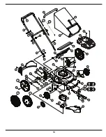
Page 14: ...31 43 33 18 33 32 26 28 43 22 46 24 27 25 30 29 57 56 43 36 16 4 8 3 2 20 51 53 52 55 54 6 7 12 47 11 5 1 13 39 36 43 43 19 23B 23A 43 44 21 41 40 56 17A 49 38 61 62 42 31 48 17B 17C 63 34A 34B 9 43 58 59 ...

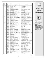
Page 15: ...dle Zag BB 734 02005A Wheel Ass y 8 x 2 125 Idle Zab Ensemble de roue 8 x 2 125 Idle Zag 734 1987 Wheel Ass y 8 x 1 8 Spoke Bar Grey Ensemble de roue 8 x 1 8 Gris 734 04033 Wheel Ass y 8 x 2 0 S Wave Ensemble de roue 8 x 2 0 S Wave 33 710 01241 Hex L Scr 1 4 15 x 1 0 Vis hex 1 4 15 x 1 0 34 746 1130 Control Cable 40 0 Lg Snap on w Honda Câble de la commande 40 0 po de lg avec Honda 746 0946 Contro...

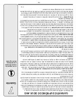
Page 16: ...s à compter de la date d achat au détail toute batterie fournie avec cette machine qui s avère défectueuse en raison d un vice de matière ou de fabrication et après que nos tests aient confirmé qu elle ne peut maintenir une charge Garantie limitée supplémentaire de trente jours sur la batterie le cas échéant MTD s engage à l expiration de la période de quatre vingt dix 90 jours et avant la fin d u...

Page 17: ...hauffe 1 Faites le plein d huile du carter 2 Consultez la notice d utilisation du moteur 3 Démontez l habitacle du ventilateur et nettoyez le 4 Consultez la notice d utilisation du moteur 1 Niveau d huile trop bas 2 Le filtre à air est sale 3 La circulation d air est gênée 4 La carburateur est mal régle Le moteur hésite parfois à régime élevé 1 Réglez l écartement à 0 030 po Con sultez la notice d...

Page 18: ...ion Bottom ou le numéro de pièce apparaît à l opposé de l adaptateur Alignez le support de la lame sur celle ci en enfonçant les pattes dans les trous de la lame puis insérez le boulon hex 10 Serrez le boulon hex au couple recommandé ci dessous Couple de montage de la lame Boulon centrale 450 po lb min 600 po lb max Vérifiez périodiquement que TOUS les écrous et boulons de la machine sont bien ser...

Page 19: ...entretien du moteur 2 Utilisez l huile à moteur recommandée dans la notice d utilisation du moteur fournie avec la tondeuse Lisez attentivement les instructions et suivez les 3 Dans des conditions normales nettoyez le filtre à air recommandée dans la notice d utilisation du moteur fournie avec la tondeuse Nettoyez le à intervalles plus rapprochés dans des conditions très poussiéreuses Une mauvaise...

Page 20: ...âchez la poignée de commande de la lame pour arrêter le moteur et la lame AVERTISSEMENT La lame continue à tourner pendant quelques secondes après que le moteur s est éteint 2 Débranchez le fil de la bougie et mettez le à la masse contre le moteur pour empêcher tout démarrage accidentel lorsque la machine n est pas surveillée Utilisation de la tondeuse AVERTISSEMENT N utilisez jamais la tondeuse s...

Page 21: ...caoutchouc recouvre l extrémité du fil de la bougie assurez vous que la boucle métal lique au bout du fil de la bougie dans la gaine en caoutchouc est bien fixée sur l embout métallique de la bougie Mise en marche du moteur 1 Si votre tondeuse est équipée d un amorceur amorcez le moteur en suivant les instructions de la notice d utilisation du moteur 2 Tenez vous derrière la machine appuyez sur la...

Page 22: ...r de coupe de la tondeuse Pour changer la hauteur de coupe poussez le levier de réglage des roues vers la roue et déplacez le vers le haut ou le bas à la hauteur choisie Voir la Figure 6 7 Assemblage du sac à herbe a Glissez le sac sur l armature côté en plastique noir sur le dessous Enfoncez les crochets de l armature dans les trous des glissières en plastique du sac à herbe Voir la Figure 7 b At...

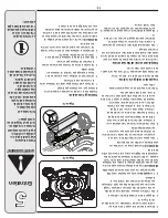
Page 23: ...n 3 Placez une goupille épingle dans l un des trous de la goupille soudée de chaque côté du guidon inférieur a Enlevez les goupilles fendues placées dans le trou extérieur des goupilles soudées sur les supports de montage du guidon Placez les goupilles fendues dans le trou intérieur Voir la Figure 3 b Placez un boulon ordinaire dans le sachet de boulonnerie fourni avec la machine dans le trou supé...

Page 24: ... 2 Avant de nettoyer de réparer ou d examiner la machine vérifiez que la lame et toutes les pièces mobiles se sont immobilisées Débranchez le fil de la bougie et mettez le à la terre contre le moteur pour empêcher tout démarrage accidentel 3 Verifiez souvent que la lame et les boulons de montage du moteur sont bien serrés Examinez visuellement la lame pour détecter toute usure excessive tout fendi...

Page 25: ... graves Si vous estimez que vous perdez votre équilibre lâcher la poignée de commande de la lame immédiatement et la lame arrêtera de tourner dans trois secondes 19 Utilisez la tondeuse seulement dans la lumière du jour ou dans la bonne lumière artificielle Marchez ne courrez pas 20 Arrêtez la lame avant de traverser des allées trottoirs ou chemins recouverts de gravier 21 Si la machine commence à...

Page 26: ...ous blesser Utilisez les tracteurs À SIÈGE parallèlement à la pente jamais en travers Utilisez les tracteurs À POUSSER perpendicu lairement à la pente jamais parallèlement 15 Visez et alignez avec un arbre ou un poteau de clôture le coin d un bâtiment o P l i e z s u r l e p o i n t i l l é q u i r e p r é s e n t e u n e d é c l i v i t é d e 1 5 Server vous de cet inclinomètre pour déterminer le...

Page 27: ...en et Remisage hors saison 10 Dépannage 12 Garantie 13 Pièces détachées voir la page 14 de la version anglaise de cette notice d utilisation Service après vente 1 Si l assemblage de cette machine vous pose des problèmes ou pour toute question concernant les commandes le fonc tionnement ou l entretien de la machine appelez le service après vente au Préparez vos numéros de modèle et de série avant d...

Page 28: ...lages Entretien Dépannage Listes des pièces détachées Garantie NOTICE D UTILISATION IMPORTANT LISEZ ATTENTIVEMENT LES RÈGLES DE SÉCURITÉ ET LES INSTRUCTIONS AVANT DE METTRE EN MARCHE LA MACHINE LES DISTRIBUTIONS RVI LIMITÉE 2955 JEAN BAPTISTE DESCHAMPS LACHINE QUEBEC H8T 1C5 769 2853A 11 26 07 ...

Reviews: