background image

13

CHIMNEY AND VENT PIPE CONNECTION

 WARNING

Installing or venting a boiler or any other gas 

appliance with improper methods or materials could 

result in death or serious injury due to 

fi

 re or to 

asphyxiation from poisonous gases such as carbon 

monoxide which is odorless and invisible.

!


Boiler and venting installations shall be performed 

in accordance with "Venting of Equipment", of the 

National Fuel Gas Code, ANSI Z223.1/NFPA 54, or 

applicable provisions of the local building codes.

Chimney Inspection

Chimney must be clean, right size, properly constructed 

and in good condition. 
Installation must conform to requirements of the authority 

having jurisdiction or, in absence of such requirements, to 

the National Fuel Gas Code, ANSI Z223.1/NFPA 54. See 

Figure 9, page 14.

Connecting Vent Damper and Vent Connector

Vent or vent connector shall be Type B or metal pipe 

having resistance to heat and corrosion not less than that 

of galvanized sheet steel not less than No. 26 gauge. See 

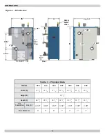
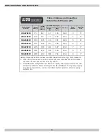
Table 1 for size of vent (

fl

 ue opening).

1. 

Position furnished vent damper on top of 

fl

 ue outlet 

collar. Fasten damper securely to 

fl

 ue outlet collar with 

sheet metal screws.
• Verify 1/2 square inch (approximately 3/4" diameter) 

hole in damper blade is plugged using plug supplied 

with vent damper.

• Verify damper blade has clearance to operate inside 

of diverter.

• Do not modify draft diverter or vent damper.

2. 

Install vent damper to service only single boiler for 

which it is intended. 
• Damper position indicator shall be in visible location 

following installation. 

• Locate damper so it is accessible for servicing.

Optional -

 damper may be installed in horizontal or 

vertical position as close to 

fl

 ue outlet as possible. 

• Horizontal installations. See Figure 10, page 15.
• Alternate installations


see steps below. See Figure 11 

page 15.

A.  Do not install vent damper on vent pipe curve.
B.  Do not run wires near high temperature surfaces. 

Use stand-off brackets 

if necessary.

3. 

Damper must be in open position when appliance main 

burners are operating.

4. 

Boiler is equipped with factory wired harness that plugs 

into vent damper. Connect thermostat to orange and 

white wires marked 24 volt thermostat on boiler.

5. 

Vent pipe must be same size as 

fl

 ue outlet collar.

6. 

Slope pipe up from boiler to chimney not less than 1/4” 

per foot.

7. 

Run pipe as directly as possible with as few elbows as 

possible.

8. 

Do not connect to 

fi

 replace 

fl

 ue.

9. 

End of vent pipe must be 

fl

 ush with inside face of 

chimney 

fl

 ue.

10. 

Horizontal run should not be longer than 3/4 the 

chimney height (HT).


See Figure 9 page 14.

Vent Pipe

•  Fasten sections of vent pipe with 3 sheet metal screws 

at each joint to make piping rigid. 

•  Support horizontal portions of vent system to prevent 

sagging. 

•  Use stovepipe wires or metal strapping every 5’ to 

support pipe from above. 

•  Vent pipe through crawl space, use double wall vent 

pipe. 

•  Vent pipe passing through combustible wall or partition, 

use ventilated metal thimble. Thimble should be 4" 

larger in diameter than vent pipe.

NOTICE

Minimum Vent Pipe Clearance - Wood and other 

combustible materials must not be closer than 6” 

from any surface of single wall metal vent pipe. 

Listed Type B vent pipe or other listed venting 

systems shall be installed in accordance with their 

listing.

Removing Existing Boiler from Common Venting 

System

When an existing boiler is removed from a common 

venting system, the common venting system is likely to be 

too large for proper venting of the appliances remaining 

connected to it.
At the time of removal of an existing boiler, the following 

steps shall be followed with each appliance remaining 

connected to the common venting system placed in 

operation, while the other appliances remaining connected 

to the common venting system are not in operation.

1. 

Seal any unused openings in the common venting 

system.

2. 

Visually inspect the venting system for proper size and 

horizontal pitch and determine there is no blockage or 

restriction, leakage, corrosion and other de

fi

 ciencies 

which could cause an unsafe condition.

Summary of Contents for CEG E Series

Page 1: ...nt Ignition Manufactured by ECR International Inc 2201 Dwyer Avenue Utica NY 13501 web site www ecrinternational com Models CEG075EID CEG112EID CEG150EID CEG187EID CEG225EID CEG262EID CEG299EID COLUMBIA COMPANY Main offices and Factory Pottstown PA CLICK ANYWHERE on THIS PAGE to RETURN to COLUMBIA BOILERS FURNACES at InspectApedia com ...

Page 2: ...8 14 1 8 17 3 8 20 5 8 23 7 8 27 1 8 30 3 8 Height B 35 7 8 Depth C 28 3 8 28 3 8 29 3 8 30 3 8 30 3 8 30 3 8 30 3 8 Gas Connection Size G NPT NPT NPT NPT NPT NPT NPT Flue Diameter 5 5 6 7 7 7 7 DIMENSIONS A 2 NPT NPT Plug 2 NPT Safety Relief Valve Floor B 5 Depth C 29 25 12 16 13 2 NPT 2 NPT ...

Page 3: ...188 141 587 83 0 7 7 CEG262EID 262 219 164 685 83 2 8 7 CEG299EID 299 250 188 782 83 4 9 7 Heating Capacity and AFUE are based on DOE Department of Energy test procedures 1 Input rating for sea level to 2 000 ft above sea level Altitudes over 2000 ft above sea level reduce input rate 4 for every 1000 ft 2 Net AHRI steam ratings shown are based on a piping and pickup allowance of 1 333 Consult manu...

Page 4: ...for use in closed heating systems where all steam is returned as condensate and make up water is minimal Boiler is not designed for or intended for use in open systems using 100 make up water Prior to Installation Verify correct boiler for type of gas being used natural or propane See Rating Plate Verify boiler size and dimensions See Figure 1 and Table 1 page 2 Verify ratings and capacity data fo...

Page 5: ...rical shock hazard Improper installation could result in death or serious injury Read this manual and understand all requirements before beginning installation Become familiar with symbols identifying potential Become familiar with symbols identifying potential hazards hazards This is the safety alert symbol Symbol alerts you to This is the safety alert symbol Symbol alerts you to potential person...

Page 6: ... 12 6 Notify owner to keep air passages free of obstruction Ventilating and combustion air must enter boiler room without restrictions Table 3 Minimum Clearance Dimensions Top 6 Rear 6 Control Side 7 Opposite Side 6 Front Alcove Flue Vent Connector 6 Near Boiler Piping 1 2 7 Install boiler so automatic gas ignition system components are protected from water dripping spraying rain etc during applia...

Page 7: ...lt in death or serious injury Qualified service agency is responsible for proper installation LOCATING THE BOILER Pressuretrol Assembly Installation Instructions See Figure 4 1 Attach pressuretrol assembly A to site glass assembly using proper pipe sealant 2 Remove pressuretrol cover 3 Route wire harness through black plastic bushing B 4 Attach two wires Wires are not polarity sensitive can place ...

Page 8: ...g or place any obstruction in discharge line Terminate freely to atmosphere where any discharge will be clearly visible and at no risk of freezing Allow complete drainage of valve and discharge line Install safety valve with spindle in vertical position Do not install shutoff valve between boiler and safety valve Support safety valve discharge piping Be short and straight as possible Terminate wit...

Page 9: ... two risers If steam main goes in two directions place two takeoffs from header one for each main 5 Recommended near boiler piping for gravity return systems is shown in Figure 8 page 11 For gravity return systems bottom of lowest steam carrying pipe dry return or end of steam main must be at least 28 above normal water level line on left side of boiler 6 Equip all boilers in gravity return system...

Page 10: ...2 2 1 7 2 2 2 1 8 2 2 3 1 9 2 2 3 1 Water Line 28 Main Vent 2 24 Equalizer 1 Close Nipple Header Floor 24 Cap To Skimmer Tee Floor Sections Risers Headers Equalizers 3 2 2 1 4 2 2 1 Water Line 28 Main Vent 2 Equalizer 1 Close Nipple Header 24 24 For Alternate Piping Configurations See Page 28 and 29 Cap To Skimmer Tee For Alternate Piping Configurations See Pages 28 and 29 Hartford Loop Hartford L...

Page 11: ...11 HYDRONIC PIPING Figure 7 Recommended Near Boiler Piping For Pumped Return Systems Figure 8 Recommended Near Boiler Piping For Gravity Return Systems ...

Page 12: ...ater than 0 60 Room volume is greater than 21 cubic feet divided by ACH air changes per hour x Total Input Mbh C Refer to National Fuel Gas Code for opening requirements between connected indoor spaces All Outdoor Air Provide permanent opening s communicating directly or by ducts with outdoors A Two Permanent Opening Method Provide opening commencing within 12 inches of top and second opening comm...

Page 13: ...stand off brackets if necessary 3 Damper must be in open position when appliance main burners are operating 4 Boiler is equipped with factory wired harness that plugs into vent damper Connect thermostat to orange and white wires marked 24 volt thermostat on boiler 5 Vent pipe must be same size as flue outlet collar 6 Slope pipe up from boiler to chimney not less than 1 4 per foot 7 Run pipe as dir...

Page 14: ...r smoke from a cigarette cigar or pipe 6 After it has been determined that each appliance remaining connected to the common venting system properly vents when tested as outlined above return doors windows exhaust fans fireplace dampers and any other gas burning appliance to their previous conditions of use 7 Any improper operation of the common venting system should be corrected so the installatio...

Page 15: ...nous gases such as carbon monoxide which is odorless and invisible Manual Operation of Vent Damper Place vent damper in open position to permit burner operation by using HOLD DAMPER OPEN switch located on damper controller Thermostat controls burner firing as before while damper remains open DO NOT turn damper open manually motor damage will result Set switch to AUTOMATIC OPERATION to close vent d...

Page 16: ...e suitable for natural and liquefied petroleum gas Install field sourced manual main shutoff valve ground joint union and sediment trap upstream of gas valve See Figure 13 Propane Installation WARNING Fire explosion asphyxiation hazard Verify boiler is equipped with propane gas orifices and gas valve is configured for propane Failure to follow these instructions may result in serious injury or dea...

Page 17: ...electrical supply to primary leads on 24 volt transformer Securely fasten with wire nuts Thermostat Installation 1 Install thermostat on inside wall per manufacturer s instructions 2 NEVER install thermostat on outside wall 3 Do not install thermostat where it will be affected by drafts hot or cold pipes sunlight lighting fixtures televisions fireplace or chimney 4 Check thermostat operation by ra...

Page 18: ...g Immediately call your gas supplier from a neighbor s phone Follow gas supplier s instructions If you cannot reach your gas supplier call the fire department 1 STOP Read the safety information on this page 2 Set the thermostat to lowest setting 3 Turn off all electric power to the appliance 4 This appliance is equipped with an ignition device which automatically lights the pilot Do not try to lig...

Page 19: ...el when boiler is off and cold when all water in the system is inside the boiler and return piping below water line and everything above water line is air no steam When boiler is making steam water level drops two to three inches below normal water line Thermostat A Set thermostat to desired room temperature B Set thermostat to lower setting if heat is not required C System is self checking If fai...

Page 20: ... outer mantel with no yellow Remain still when observing main burner flames Check main burner orifices burner throat and flame ports for dust and lint obstruction if flame appearance is not correct Remove rollout shield if necessary to observe main burner flames See Figure 16 Replace rollout shield after observation Gas Valve Safety Shutdown Test 1 Test ignition system safety shutoff device after ...

Page 21: ...G Checking Controls Low Water Cut Off A Turn off power to boiler or turn thermostat down to lowest setting B Drain water to below visible bottom of water gauge glass Turn power on and turn thermostat to call for heat C Gas valve opens for approximately 15 seconds time delay on probe type LWCO gas valve will close and red indicator illuminates on LWCO D When water is restored it waits 30 seconds be...

Page 22: ...ction from boiler drain valve to safe discharge point outside Shut off gas burners open drain valve allow all of water in boiler to drain out Close drain valve Allow boiler to cool slowly refill boiler to water line Repeat this step as many times as necessary until blow down water is clear START UP CLEANING 7 Following final blow down allow boiler to cool Add fresh water slowly up to normal water ...

Page 23: ...us bead of 400 F RTV silicone to four mounting surface flanges of flue collector Mount flue collector on heat exchanger Tighten nuts and bolts 6 Seal front edge and four corners of flue collector to heat exchanger with silicone sealant 7 Use flashlight to verify there are no gaps in silicone seal 8 Install draft diverter vent damper vent pipe and jacket top and front cover 9 Reassemble all parts 1...

Page 24: ...tact service technician No electric power to boiler Verify electric power supply circuit is ON Contact your service technician to verify over current protection Controls out of adjustment Reset according to instructions Radiators not heating Inspect steam air vents for proper operation Contact service technician to inspect for faulty steam traps Poor electrical contact Contact your service technic...

Page 25: ...Optional Optional water feeder connection Connect feeder N to terminal 2 Connect feeder H to terminal 1 Connect FEED or W to terminal A For water feeders with 2 leads connect feeder common to terminal 2 and feeder hot to terminal A Note Use of a solenoid valve or McDonnell Miller Model 101A water feeder may cause flooding and is not recommended for use with this low water cut off ...

Page 26: ...DUCTORS ONLY GAS VALVE MV MV PV PV GRN BLU WHT RED INSIDE BOILER JACKET OUTSIDE BOILER JACKET ROLL OUT SWITCH WHT BLU IGNITION MODULE RED WHT BLU PRESSURETROL DIFF KG 2 CM PSI 6 5 3 1 2 8 9 0 5 CUT IN BLK BLK BLK WHT WHT BLOCKED VENT SWITCH WHT BLK 120V 24V 50VA TRANSFORMER LWCO PROBE BLK BRN YEL ORG NEC CLASS 2 LOW VOLTAGE FIELD SUPPLIED THERMOSTAT T R T W LOW WATER CUT OFF PROBE JP2 2 1 P1 P2 A ...

Page 27: ...NOTE CONNECTOR POSITION 3 IS LABELED 1 ON LWCO CIRCUIT BOARD JP2 MOLEX CONNECTOR PRESSURETROL BLOCKED VENT SWITCH THERMOSTAT ROLL OUT SWITCH 1 3 VENT DAMPER IGNITION MODULE 24V 24V GND PV GND BURNER MV SPARK SENSE MV PV PROBE JP1 BURNER JP1 P1 JP1 A JP1 1 JP1 2 2 4 MV PV MV GAS VALVE GND PV JP1 P2 SPARK IGNITOR LOW WATER CUT OFF PROBE R C HIGH VOLTAGE CONNECTIONS PER NEC AND LOCAL CODES NEC CLASS ...

Page 28: ...28 OPTIONAL HYDRONIC PIPING Figure 21 Counter Flow Steam Systems Hartford Loop Water Lin 28 48 24 Floor 2 Pipe Floor 24 ...

Page 29: ...29 Figure 22 Drop Header for True Swing Joint Water Line 28 24 Hartford Loop Floor 24 OPTIONAL HYDRONIC PIPING e ...

Page 30: ...30 OPTIONAL PIPING HYDRONIC PIPING ...

Page 31: ...31 SERVICE RECORD Company Address Phone Company Name Tech Initials Service Performed Date ...

Page 32: ...Columbia P O Box 24202 Baltimore Maryland 21227 ...

Reviews: