background image

16

4

Operating 

Your Lawn 

Tractor

If you strike a foreign 

object, stop the 

engine, disconnect the 

spark plug wire(s) and 

ground against the 

engine. Thoroughly 

inspect the machine 

for any damage. 

Repair the damage 

before restarting and 

operating.

Avoid sudden starts, 

ex-cessive speed and 

sudden stops.

Do not leave the seat 

of the tractor without 

first placing the PTO 

(Blade Engage) lever 

in the disengaged 

(OFF) position, 

depressing the brake 

pedal and engaging 

the parking brake. If 

leaving the tractor 

unattended, also turn 

the ignition key off 

and remove the key.

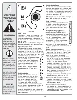
IMPORTANT: Do NOT hold the key in the START 
position for longer than ten seconds at a time. Doing so 
may cause damage to your engine’s electric starter.

6.  After the engine starts, deactivate the choke control 

and place the throttle control in the FAST position.

NOTE: Do NOT leave the choke control on while operat-
ing the tractor. Doing so will result in a “rich” fuel mixture 
and cause the engine to run poorly. 

Stopping the Engine

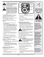
WARNING: If you strike a foreign 

object, stop the engine, disconnect the 
spark plug wire(s) and ground against 
the engine. Thoroughly inspect the 
machine for any damage. Repair the 
damage before restarting and operat-
ing the tractor.

1.  If the blades are engaged, place the PTO (Blade 

Engage) lever in the disengaged (OFF) position.

2.  Turn the ignition key counterclockwise to the STOP 

position. 

3.  Remove the key from the ignition switch to prevent 

unintended starting.

Driving The Tractor

WARNING: Avoid sudden starts, 

ex-cessive speed and sudden stops.
WARNING: Do not leave the seat 
of the tractor without first placing 
the PTO (Blade Engage) lever in the 
disengaged (OFF) position, depress-
ing the brake pedal and engaging the 

parking brake. If leaving the tractor 
unattended, also turn the ignition key 
off and remove the key.
WARNING: Always look down and 
behind before and while backing up to 
avoid a back-over accident.

1.  Depress the brake pedal to release the parking brake 

and let the pedal up. 

2.  Move the throttle lever into the FAST (rabbit) posi-

tion.

3.  Place the shift lever in either the FORWARD or 

REVERSE position.

IMPORTANT: Do NOT use the shift lever to change the 
direction of travel when the tractor is in motion. Always 
use the brake pedal to bring the tractor to a complete 
stop before shifting.

4.  Release the parking brake by depressing the clutch-

brake pedal and positioning the speed control lever 
in desired position.

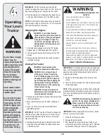
WARNING

AVOID SERIOUS INJURY OR 

DEATH

•  GO UP AND DOWN SLOPES, NOT ACROSS. 

•  AVOID SUDDEN TURNS.

•  DO NOT OPERATE THE UNIT WHERE IT COULD SLIP OR TIP.

•  IF MACHINE STOPS GOING UPHILL, STOP BLADE(S) AND 

BACK DOWNHILL SLOWLY.

•  DO NOT MOW WHEN CHILDREN OR OTHERS ARE AROUND.

•  NEVER CARRY CHILDREN, EVEN WITH BLADES OFF.

•  LOOK DOWN AND BEHIND BEFORE AND WHILE BACKING.

•  KEEP SAFETY DEVICES (GUARDS, SHIELDS, AND 

SWITCHES) IN PLACE AND WORKING.

•  REMOVE OBJECTS THAT COULD BE THROWN BY THE 

BLADE(S).

•  KNOW LOCATION AND FUNCTION OF ALL CONTROLS.

•  BE SURE BLADE(S) AND ENGINE ARE STOPPED BEFORE 

PLACING HANDS OR FEET NEAR BLADE(S).

•  BEFORE LEAVING OPERATOR’S POSITION, DISENGAGE 

BLADE(S), PLACE THE SHIFT LEVER IN NEUTRAL, ENGAGE 
BRAKE LOCK, SHUT ENGINE OFF AND REMOVE KEY.

READ OPERATOR’S MANUAL

IMPORTANT: First-time operators should use speed posi-
tions 1 or 2. Become completely familiar with the tractor’s 
operation and controls before operating the tractor in 
higher speed positions.

5.  Release clutch-brake pedal slowly to put unit into 

motion.

6.  The lawn tractor is brought to a stop by depressing the 

clutch-brake pedal.

NOTE: When operating the unit initially, there will be little 
difference between the highest two speeds until after the 
belts have seated themselves into the pulleys during the 
break-in period.

WARNING: Before leaving the operator’s 
position for any reason, disengage the 

blades, place the shift lever in neutral, 
engage the parking brake, shut engine 
off and remove the key.

IMPORTANT: When stopping the tractor for any reason 
while on a grass surface, always:

1.  Place the shift lever in neutral, 
2.  Engage the parking brake, 
3.  Shut engine off and remove the key. Doing so will 

minimize the possibility of having your lawn ‘‘browned’’ 
by hot exhaust from your tractor’s running engine.

WARNING

Summary of Contents for Columbia 76G

Page 1: ...INTED IN U S A IMPORTANT READ SAFETY RULES AND INSTRUCTIONS CAREFULLY BEFORE OPERATION OPERATOR S MANUAL 769 04781 1 16 09 LES DISTRIBUTIONS RVI LIMITÉE 2955 JEAN BAPTISTE DESCHAMPS LACHINE QUEBEC H8T 1C5 MTD LLC P O BOX 361131 CLEVELAND OHIO 44136 0019 Lawn Tractor Model 76G ...

Page 2: ...you have difficulty assembling this product or have any questions regarding the controls operation or maintenance of this unit please call an authorized dealer Please have your unit s model number and serial number ready when you call See previous section to locate this information 2 The engine manufacturer is responsible for all engine related issues with regards to performance power rating speci...

Page 3: ... and you could slip resulting in serious injury Operate RIDING mowers up and down slopes never across the face of slopes Operate WALK BEHIND mowers across the face of slopes never up and down slopes Sight and hold this level with a vertical tree or a corner of a building or a fence post F o l d a l o n g d o t t e d l i n e r e p r e s e n t s a 1 5 s l o p e 15 Use this page as a guide to determi...

Page 4: ...it until the blade s come to a complete stop before removing grass catcher emptying grass unclogging chute removing any grass or debris or making any adjustments 21 Never leave a running machine unattended Always turn off blade s place transmission in neutral set parking brake stop engine and remove key before dismounting 22 Use extra care when loading or unloading the machine into a trailer or tr...

Page 5: ...and turn machine off if a child enters the area c Before and while backing look behind and down for small children d Never carry children even with the blade s shut off They may fall off and be seriously injured or interfere with safe machine operation e Use extreme care when approaching blind corners doorways shrubs trees or other objects that may block your vision of a child who may run into the...

Page 6: ...e while the engine is running 11 Grass catcher components and the discharge cover are subject to wear and damage which could expose moving parts or allow objects to be thrown For safety protection frequently check components and replace immediately with original equipment manufacturer s O E M parts only listed in this manual Use of parts which do not meet the original equipment specifications may ...

Page 7: ...NG BLADES Never carry passengers Never carry children even with the blades off DANGER ROTATING BLADES Always look down and behind before and while backing to avoid a back over accident WARNING ROTATING BLADES Do not put hands or feet near rotating parts or under the cutting deck Contact with the blade s can amputate hands and feet WARNING THROWN OBJECTS This machine may pick up and throw and objec...

Page 8: ... throwing objects Failure to operate the riding mower without the discharge cover in the proper operating position could result in serious personal injury and or property damage Attaching The Steering Wheel If the steering wheel for your tractor did not come attached the hardware for attaching it has been packed within the steering wheel beneath the steering wheel cap Carefully pry off the steerin...

Page 9: ...ng wheel cap over the center of the steering wheel and push downward until it clicks into place IMPORTANT Do NOT overtighten Figure 3 2 Figure 3 3 Figure 3 4 Attaching the Hood Scoop If so equipped If the hood scoop was not secured to the hood of your tractor at the factory you will find it in a plastic bag hanging from the throttle lever To install 1 Carefully pivot the tractor hood forward 2 Rem...

Page 10: ...eat form its shipping position and remove the hex screw or knob from the bottom of seat before proceeding with applicable instructions below 1 Position the shoulder screws found on the base of the seat inside the slot openings in the seat pivot bracket Figure 3 5 or Figure 3 6 2 Slide the seat slightly rearward in the seat pivot bracket lining up the rear slots in the pivot bracket with the remain...

Page 11: ...nt and proceed as follows 1 Select the height position of the cutting deck by plac ing the deck lift lever in the normally desired mowing height setting any of the six different cutting height notches on the right fender 2 Check the gauge wheels for contact or excessive clearance with the surface below The deck gauge wheels should have between inch and inch clearance above the ground as follows If...

Page 12: ...machine Failure to comply with all safety rules and instructions may rerult in personal injury If so equipped NOTE Any reference in this manual to the RIGHT or LEFT side of the tractor is observed from operator s position NOTE Steering wheel not shown for clarity For shipping reasons seats are either fastened to the tractor seat s pivot bracket with a plastic tie or mounted backward to the pivot b...

Page 13: ...ease the key into the ON position once engine has fired To stop the engine turn the ignition key counterclockwise to the OFF position Figure 4 3A The headlights are on when the engine is running Figure 4 3B To activate the headlights turn the key one more position to the left The engine will continue to run with the headlights on Ignition Switch Module If Equipped To start the engine insert the ke...

Page 14: ...ever to the left then place in the notch best suited for your applica tion PTO Blade Engage Lever Found on the tractor s right fender the PTO blade engage lever is used to engage power to the cutting deck or other separately available attachments To operate move the lever all the way forward Moving the lever all the way rearward into the PTO OFF position disengages power to the cutting deck attach...

Page 15: ...ll the way down and into the parking brake position 3 Release the clutch brake pedal to allow the parking brake to engage To release the parking brake 1 Depress the clutch brake pedal and move the speed control lever out of the parking brake position and into a desired speed Setting the Cutting Height 1 Select the height position of the cutting deck by placing the deck lift lever in any of the dif...

Page 16: ...rottle lever into the FAST rabbit posi tion 3 Place the shift lever in either the FORWARD or REVERSE position IMPORTANT Do NOT use the shift lever to change the direction of travel when the tractor is in motion Always use the brake pedal to bring the tractor to a complete stop before shifting 4 Release the parking brake by depressing the clutch brake pedal and positioning the speed control lever i...

Page 17: ...se and if the operator leaves the seat Refer to Safety Interlock Switches on page 14 Using the Deck Lift Lever To raise the cutting deck move the deck lift lever to the left then place it in the notch best suited for your application Refer to Setting The Cutting Height earlier in this section Mowing WARNING To help avoid blade contact or a thrown object injury keep bystand ers helpers children and...

Page 18: ...ly remove the mulch plug by unthreading the plastic wing nut which fastens it to the cutting deck This will allow the clippings to discharge out the side See Figure 4 6 Headlights On some models the lamps are ON whenever the tractor s engine is running On other models the lamps are ON whenever the ignition key is moved out of the STOP position On all models the lamps turn OFF when the ignition key...

Page 19: ...djustment is achieved Side to Side If the cutting deck appears to be mowing unevenly a side to side adjustment can be performed Adjust if necessary as follows 1 With the tractor parked on a firm level surface place the deck lift lever in the top notch highest position and rotate both blades so that they are perpendicular with the tractor 2 Measure the distance from the outside of the left blade ti...

Page 20: ...ne model found on your tractor it may be necessary to remove the tractor s side panel in order to replace the oil filter if so equipped Figure 6 2 Figure 6 1 Lubrication WARNING Before lubricating repairing or inspecting always disengage PTO move shift lever into neutral position set parking brake stop engine and remove key to prevent unintended starting Engine Lubricate the engine with motor oil ...

Page 21: ...ctor sPTO BladeEngage intotheOFF position 11 TurntheignitionkeytotheSTOPpositiontoturnthetractor s engineoffandengagetheparkingbrake 12 Turnthewateroffanddetachthehosecouplerfromthe waterportonyourdeckssurface 13 Repeatsteps4 11ontheoppositesideofthecuttingdeck Cutting Deck Removal NOTE Models equipped with a 38 inch deck have one deck idler pulley Models equipped with a 42 inch or 46 inch deck ha...

Page 22: ...ect terminals reversing them could change the polarity and result in damage to your engine s alternating system Charging IMPORTANT When charging your tractor s battery use only a charger designed for 12V lead acid batteries Read your battery charger s Owner s Manual prior to charging your tractor s battery Always follow its instructions and heed its warnings If your tractor has not been put into u...

Page 23: ...ade s for sharpening or replace ment Protect your hands by using heavy gloves or a rag to grasp the cutting blade WARNING Periodically inspect the blade spindles for cracks or damage especially if you strike a foreign object Replace immediately if damaged The blades may be removed as follows 1 Remove the deck from beneath the tractor refer to 6 Maintaining Your Lawn Tractor WARNING Be sure to shut...

Page 24: ... from around the engine pulley 4 On the 42 inch deck only loosen but do not remove the idler pulley nuts This will enable the belt to be easily removed from the idler pulleys See Fig 6 10 Engine Pulley 38 Inch Deck Idler Bracket Deck Idler Pulleys Figure 6 11 Periodically inspect the blade spindles for cracks or damage especially if you strike a foreign object Replace immediately if damaged Be sur...

Page 25: ... Decks NOTE Several components must be removed in order to change the tractor s lower deck belt See an authorized Service Dealer to have your lower drive belt replaced or phone Customer Support as instructed on page 2 for informa tion on ordering a Service Manual Changing the Transmission Drive Belt NOTE Several components must be removed and special tools i e air impact wrench in order to change ...

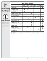
Page 26: ...t Change Engine Oil Replace Oil Filter Clean Battery Terminals Lube Front Axles and Rims Clean Engine Cooling Fins Lube Front Deck Wheels if equipped Lube Deck Spindles Lube Pedal Pivot Points Check Spark Plug Condition Gap Replace Fuel Filter IMPORTANT Check air cleaner components more often if operating in extremely dirty dusty conditions and service as necessary 6 Maintaining YourTractor IMPORT...

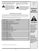
Page 27: ...hes dryer or other gas appliance Attachments Accessories MODEL DESCRIPTION OEM 190 032 42 inch Two stage Snow Thrower OEM 190 116 38 42 inch Deck Mulch Kit OEM 190 180 Twin Bagger Grass Collector for 38 42 inch Decks OEM 190 182 Twin Bagger Grass Collector for 46 inch Decks OEM 190 183 Deck Wheel Kit OEM 190 215 Wheel Weight OEM 190 607 Deluxe Tractor Sunshade OEM 190 658 Tire Chains 20 x 8 Tires ...

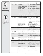
Page 28: ...idge element or clean pre cleaner if so equipped 1 Unit running with CHOKE applied 2 Spark plug wire s loose 3 Blocked fuel line or stale fuel 4 Vent in gas cap plugged 5 Water or dirt in fuel system 6 Dirty air cleaner Engine overheats 1 Fill crankcase with proper oil 2 Clean grass clippings and debris from around the engine s cooling fins and blower housing 1 Engine oil level low 2 Air flow rest...

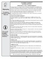
Page 29: ...ents clutch adjustments deck adjustments and normal deterioration of the exterior finish due to use or exposure d Service completed by someone other than an authorized service dealer e MTD does not extend any warranty for products sold or exported outside of Canada including possessions and territories f Replacement parts that are not genuine MTD parts g Transportation charges and service calls h ...

Page 30: ... AGAINST THESE COMPONENTS MUST BE HANDLED THROUGH THE RESPECTIVE MANUFACTURERS SERVICE DEALERS Belts light bulbs clutch parts friction wheels grass bags tires seats rider deck wheels and cutting blades are covered by a 60 day limited warranty Batteries are warranted against defect for 90 days at 100 of their value and 50 of their value for the period between the 91st day and the 120th day Fuses sh...

Page 31: ... Deck two each 618 0240A Deck Wheels 734 0973 Battery 725 1707D Tire Front 15 x 6 x 6 Square Shoulder 734 1731 Tire Rear 20 x 8 x 8 Square Shoulder 734 1730 Hub Cap 731 0484A Fuel Tank Cap 951 3111 Throttle Choke Control Cable Single Cylinder Engines 746 04364 Choke Control Cable Twin Cylinder Engines 746 1085A Throttle Control Cable Twin Cylinder Engines 746 04365 Discharge Chute Assembly 931 103...

Page 32: ...p Inc s application for certification The warranty period begins on the date the lawn mower is delivered to an ultimate purchaser or first placed into service The warranty period is two years Subject to certain conditions and exclusions as stated below the warranty on emission related parts is as follows 1 Any warranted part that is not scheduled for replacement as required maintenance in the writ...

Page 33: ...ring System Cold start enrichment system soft choke Carburetor and internal parts Fuel pump Fuel tank 2 Air Induction System Air cleaner Intake manifold 3 Ignition System Spark plug s Magneto ignition system 4 Exhaust System Catalytic converter SAI Reed valve 5 Miscellaneous Items Used in Above System Vacuum temperature position time sensitive valves and switches Connectors and assemblies 6 Evapor...

Reviews: