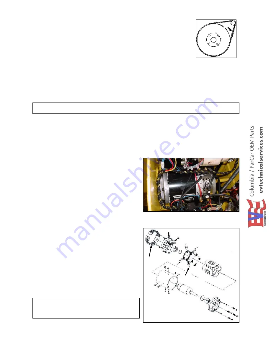
Figure 4.5.1
Figure 4.5.2
Tension Adjustment:
Lift the rear of the vehicle and remove the drive wheel.
Loosen the 4 drive motor mounting bolts (Fig. 4.4.2) and jam nut on the drive
motor adjusting screw. Turning motor adjusting screw towards motor will
tighten drive chain. Turning adjusting screw away from motor will loosen
drive chain. With motor mounting bolts tight, proper chain deflection is no
more than 0.50' (1/2 inch). See arrow Fig. 4.4.3.
Torque motor mounting bolts to 150 inch pounds and tighten the jam nut
(Fig. 4.4.1 B) on motor adjusting screw.
Install drive wheel.
4.5 DRIVE MOTOR
To remove the drive motor (Figure 4.5.1):
Remove the charger cover plate.
Disconnect the wires from the motor, noting their locations for reinstallation.
NOTICE:
T
o avoid possible internal motor damage when removing or installing cables, use a
wrench to hold the bottom nut and stud for loosening or tightening the top nut.
Lift the rear of the vehicle and remove the rear drive wheel.
Loosen the four motor mounting bolts (Fig. 4.4.2) and nut on the motor adjusting bolt (Fig. 4.4.1).
Loosen the motor adjusting screw several turns.
Slide the motor toward the rear of the vehicle and remove the drive chain.
Support the motor and remove the four mounting bolts.
Slide the motor to the left until the drive sprocket is clear of the frame and lift the motor up from the
vehicle.
To install drive motor:
Place the motor in the frame with the wire
terminals as shown in Figure 4.5.1.
Once in place, install the top motor mounting bolt
first, then install the remaining three motor
mounting bolts (Fig. 4.4.2). Do not tighten.
Install the drive chain and adjust as stated in
Section 4.4.
Install the rear drive wheel. Torque wheel nuts in
a crossing pattern, to 65-ft. lbs.
Connect the wire leads to the motor.
To remove and install motor brushes (Fig. 4.5.2):
Remove motor as described above and remove
the inspection headband (A).
For each brush, remove the screw (B) from the
brush lead, pull the brush spring away from the
brush and remove the brush.
To install, pull brush spring away from the brush
holder, set the brush in the brush holder and
release spring.
Install screw into the brush lead.
Install the inspection headband and replace
motor.
NOTICE:
Minimum brush length is 0. 50" (1/2
inch). Whenever possible, always re-surface
armature commutator when installing new
brushes.
A
B
4-4
Figure 4.4.3
Summary of Contents for CR-10 Chariot
Page 1: ......


