background image

LWLCWH   COLUMBIA BOILER COMPANY   REV. 13106

11

FUEL CONNECTIONS

OIL SUPPLY PIPING

Connect burner to oil supply.  Refer to fuel unit manufacturer literature for piping, connections, lift and
tank installation.  If such information is unavailable use the following guidelines:

Fuel supply “level with” or “above” burner: A single stage fuel unit connected to the fuel supply
with a single supply line is the most common type of installation for these conditions.  Manual vent-
ing of the fuel oil is usually required on initial start up. Failure to vent air could result in air lock/oil star-
vation.(One Pipe)

Fuel supply below the level of the burner: Use a single stage fuel pump in lift conditions of up to
10 feet and a two stage pump when lift exceeds 10 feet. Both conditions require the use of a return
line which purges the fuel pump of air, returning it to the fuel tank.  The  by-pass  plug must be insert-
ed into the fuel pump when installing a return line.(Two Pipe)

Fuel line installation: Consult the burner section of this manual for oil line type and sizing require-
ments for proper operation. The size of oil lines is extremely important for proper operation.
Continuous lengths of heavy wall copper tubing are recommended and should be installed under the
floor whenever possible. Fuel lines should not chaff the appliance or building structure.

All oil feed lines must be air tight. Use as few fittings as possible when assembling the oil lines.
Compression fittings allow more of a chance for air to be introduced into the oil supply. The slightest
air leak, usually caused by loose fittings or bad gaskets, can cause poor starts, smoky starts, soot-
ing of burner parts, inefficient operation, and a dangerous combustion condition. Always install fittings
in accessible locations.  

WARNING:

TEFLON

®

TAPE SHOULD NEVER BE USED WITH ANY OIL LINE CONNECTIONS.

THE USE OF TEFLON

®

TAPE ON BURNER COMPONENTS OR OIL SERVICE LINES

WILL VOID MOST BURNER WARRANTIES.

A vacuum test should be done on all installations to ensure that all fittings are tight and the oil lines
are of proper size.   Suction vacuums must be held to acceptable limits.

Fuel line valve and filter: (Not supplied) Install two high quality shutoff valves in accessible locations
on the oil supply line. Locate one close to the tank and the other close to the burner ahead of the fil-
ter.  Some filters come with built-in shutoff valves. Install a generous capacity filter inside the building
between the fuel tank shutoff and burner. 

For additional information consult the burner section of this manual.

Summary of Contents for CWH series

Page 1: ...L WL CWH SERIES BOILERS INSTALLATION OPERATION and MAINTENANCE MANUAL COLUMBIA BOILER COMPANY P O BOX 1070 POTTSTOWN PA 19464 PHONE 610 323 2700 FAX 610 323 7292 www columbiaboiler com COLUMBIA ...

Page 2: ......

Page 3: ...and Tank Systems Specifications and Data L Series WL Series CWH Series Replacement Parts List for L WL CWH Series Boilers Burks Turbine Pumps Impeller Adjustment Instructions Piping Layout Dwgs PL 100 PL 101 PL 099 PL 102 Corning Tubular Gage Glasses Red Line Use Care and Installation Warrick Probe Series 26 Controls Warrick Probe Assembly Replacement Parts Safety Valve Piping Typical McDonnell Mi...

Page 4: ... before installing operating or servicing your boiler 2 All cover plates enclosures and safety devices must be installed at all times except while performing maintenance and service 3 Only trained service technicians should do any work on your boiler 4 All state and local codes take precedence over any recommendations given in this manual ...

Page 5: ... returned after receiving authorization from your dealer freight pre paid to the Columbia Boiler Co 390 Old Reading Pike Pottstown PA 19464 The use of the Columbia returned goods form is mandatory when returning defective material c Columbia is not responsible for any labor cost for the removal and replacement of equipment d Equipment which is repaired or replaced will carry a warranty equal to th...

Page 6: ...C electrical service CWH Series Steam Boiler The CWH Series is a steam boiler used for indirect hot water applications This boiler classification consists of all L and WL Series Boilers providing heat transfer to one or two coils depending on boil er size The boiler is a self contained unit allowing a steam cavity above the water line for expansion Columbia hot water and low pressure steam boilers...

Page 7: ...t this information be available to assure prompt service Boiler Model and Size HP _____________________________________________________ Boiler Serial Number __________________________________________________________ Boiler National Board Number _________________________________________________ Date Installed ________________________________________________________________ Burner Type and Model ___...

Page 8: ...pection and service on burner boiler piping controls or combustion vent DO NOT install exhaust fans in or near the boiler room Exhaust fans steal available make up air dur ing burner operation and more importantly when the boiler cycles off exhaust fans pull hot flue gases back through the burner causing burner parts to deteriorate and to eventually fail premature ly Maintain a positive pressure i...

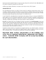
Page 9: ...ther before proceeding with jacket installation Assemble the lower front panel to one side wall at a time Next attach the lower rear panel to each side wall of the boiler When applicable mount the upper front and rear panels in their respective locations Attach the joiner plate behind the lower portion of the lower front panel as shown Finally assemble the top right and left jacket panels on top o...

Page 10: ...t insulating mate rial for a gasket as shown in Figure 2 Wet insulation is the preferred gasketing material because it compresses into a flat gasket which conforms to and fills any and all voids Secure the burner in the boiler using the four bolts supplied with the burner See the Burner Section of this manual for proper electrical wiring and fuel supply piping Note All factory packaged boilers use...

Page 11: ... Quick Hook Up Low Water Cut Off Install this device into the 2 1 2 NPT welded coupling found on the coil plate for L Series boilers and on the left hand side of the heat exchanger for WL Series boilers Water Heaters McDonnell Miller Model 767 Quick Hook Up Low Water Cut Off Install this device into the 2 1 2 NPT welded coupling found on the coil plate for CWH 170 610 Series boilers and on the lef...

Page 12: ...l should always be above the Lowest Permissible Water Level indicator label found on the left side jacket panel of the boiler Hot water boilers do not require a Water Gauge Pressure Controls Low pressure 15 PSI controls are supplied with steam units only These controls consist of an Operating Control and a Safety Limit An additional operating control may also be supplied for burn ers that function...

Page 13: ...f oxygenated water Water treatment and a water treatment program must be prac ticed or the life of the boiler will be severely limited If a Condensate Return Feedwater Tank is used connect the feedwater source to the float valve on the tank Coils Boilers are shipped with the coil s assembled to the coil plate s and mounted in the boiler For the smaller L Series L 18 CWH 170 thru L 24 CWH 390 the c...

Page 14: ...s of heavy wall copper tubing are recommended and should be installed under the floor whenever possible Fuel lines should not chaff the appliance or building structure All oil feed lines must be air tight Use as few fittings as possible when assembling the oil lines Compression fittings allow more of a chance for air to be introduced into the oil supply The slightest air leak usually caused by loo...

Page 15: ...lumn Gas pressure greater than fourteen inches water column will require an additional gas pres sure regulator to prevent damage to the primary gas regulator Gas pressure below the minimum will cause combustion efficiency problems and should be avoided if possible Low gas pressure may also prevent the boiler from obtaining the desired input rate which will cause the boiler to be unable to produce ...

Page 16: ...520 800 1700 3000 4500 9300 30 250 425 690 1400 2500 3750 7500 40 210 360 560 1200 2100 3200 6400 50 190 325 500 1100 1900 2850 5800 60 180 300 480 1000 1800 2300 4800 80 150 260 410 850 1550 2000 4200 100 135 230 370 750 1375 1680 3500 150 110 190 300 600 1100 1200 2750 200 75 165 260 540 950 1000 2000 Fitting Equivalent Lengths of Standard Pipe in Feet for Listed Fittings Std Tee 5 5 7 5 9 0 12 ...

Page 17: ...o restrictions of any kind If louvers or screens are used over combustion air openings calculate the percentage of free area to allow for these restrictions Do not have exhaust fans in the immediate proximity of the boiler room if at all possible as they will cause a reversal of draft through the boiler when the burner is cycled off This draft reversal draws heat from the combustion chamber back t...

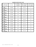
Page 18: ...CWH 170 L 20 280 000 126 12 X 12 14 CWH 240 L 22 336 000 168 14 X 14 16 CWH 300 L 24 420 000 210 15 X 15 18 CWH 390 L 30 560 000 273 17 X 17 20 CWH 475 L 32 700 000 336 19 X 19 22 CWH 610 L 60 840 000 420 21 X 21 24 CWH 780 L 90 1 260 000 630 26 X 26 30 CWH 1200 L 120 1 680 000 840 30 X 30 34 CWH 1510 L 140 1 960 000 987 32 X 32 36 CWH 1810 L 180 2 520 000 1260 36 X 36 38 CWH 2460 BOILER SIZE HORS...

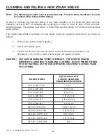
Page 19: ...e washed out by boiling as follows 1 Fill the boiler to the normal waterline 2 Remove the safety valve 3 Provide a boil out compound of caustic soda and trisodium phosphate in the proportions of 2 1 2 lbs of each chemical per 120 gallons of water CAUTION USE CARE IN HANDLING THESE CHEMICALS THE CAUSTIC SODA IS EXTREMELY CORROSIVE TO SKIN AND CLOTHING DO NOT PERMIT EITHER THE DRY MATERIAL OR THE CO...

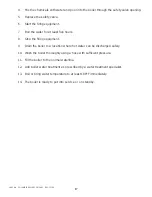
Page 20: ...five hours 8 Stop the firing equipment 9 Drain the boiler to a location where hot water can be discharged safely 10 Wash the boiler thoroughly using a hose with sufficient pressure 11 Fill the boiler to the normal waterline 12 Add boiler water treatment as prescribed by a water treatment specialist 13 Boil or bring water temperature to at least 180 F immediately 14 The boiler is ready to put into ...

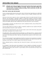
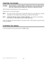
Page 21: ...s except while perform ing maintenance and service The fuel supply should not be turned on until the combustion chamber has been vented and the pilot light if gas ignited checked for proper operation All drain valves including blowdown valves for stream boilers water column drain valves gauge glass drain valves and gauge cocks should be closed The safety relief valves should be inspected externall...

Page 22: ...burner will not operate when the boiler has reached its normal water level until the reset button on the manually reset probe type low water cut off is pushed NOTE Combustion efficiency must be checked at this time See the burner manufacturers instructions for correct settings and more detailed information Follow the adjustment procedures outlined in the burner section of this manual to set up the...

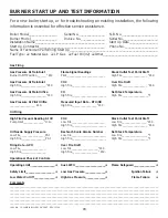
Page 23: ...um Reading At Oil CO2 Stack Outlet Test Point Draft Pump Inlet_______________ H G Low Fire________________________ Low Fire__________________ W C High Fire_________________________ High Fire__________________ W C Oil Nozzle Supply Pressure Bachrach Scale Smoke Number Net Stack Temperature Low Fire__________________PSI Low Fire_________________________ Low Fire___________________ F High Fire_______...

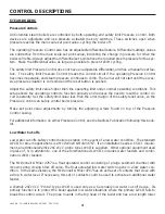
Page 24: ... control cir cuit constantly Set the safety limit value less than the error margin of the safety relief valve so the Pressure Control can safely control boiler pressure Make set point value adjustments by turning the adjusting screws found on top of the Pressure Control casing For additional information on either Pressure Control see the Danfoss Publication following this book let Low Water Cut of...

Page 25: ...ontrols use a float activated switch to control LWCO and pump control functionality For additional information on the appropriate Low Water Cut Off see the LWCO cut sheets following this booklet Safety Valve Safety valves shall be piped so that any discharge cannot cause injury to people or damage to prop erty The discharge piping must be supported so that the weight of the piping is not transmitt...

Page 26: ...4006E 130 290F like the operating Aquastat consists of an adjustable thermostatic control and separate temperature sensing immersion well This controller has a manual reset switch which must be depressed in the event that the operating circuit reached and shut off on safety For additional information on either the L4006A or L4006E see Honeywell Publication 60 2104 8 following this booklet Low Wate...

Page 27: ...d be maintained in the boiler room at all times Daily Boiler Check Maintenance List 1 Water Level Controls and Cut Offs are operating normally 2 Instrument and equipment settings are normal 3 Gauge glass is clean If leaks are detected replace glass gaskets and brass washers immediately When replacing gauge glass use only 5 8 O D Pyrex red line high pressure high temperature glass tubing with fire ...

Page 28: ...ler or Aquastat Controller 3 Test safety valves 4 Remove the Low Water Cut Off and clean inside casting 5 Oil fired clean replace oil filters or strainers if equipped 6 Oil fired replace ignition electrodes if equipped 7 Gas pilots conduct pilot turndown test 8 Gas fired replace ignition and flame rods 9 Gas fired check drip leg strainer 10 Oil fired check for refractory hold in 11 Check Automatic...

Page 29: ...ety feature inoperative 11 Without pressure on boiler and with gauge valves closed snug up the bottom nut and then the top nut with a wrench after 1 day of operation Blowdown Perform blowdown procedures on boilers that require make up water such as steam boilers Hot water and indirect hot water heaters CWH Series are closed loop systems that recirculate the same water These boilers should require ...

Page 30: ...pm Prevents scale formation Total Hardness 0 50 ppm Prevents scale formation Chlorides 60 200 ppm A measure of proper blow down Total Dissolved Solids 2000 ppm Maximum High solids may cause surging Sulfites 20 30 ppm A good oxygen scavenger Specific Conductance 700 micro ohms cm A measure of proper blowdown Oxygen 007 mg liter Prevents corrosion and pitting ppm parts per million Use proper water t...

Page 31: ...should it exceed 0 007 mg l Sulfites Sodium sulfite is generally used for the chemical removal of dissolved oxygen within the boiler water To assure the rapid and complete removal of the oxygen entering the boiler feedwater system the con centration of sulfite in the boiler must be maintained at a minimum of 20 PPM parts per million Solids Solids can be broken up into two categories suspended soli...

Page 32: ...entration of phosphates in the water to 30 50 PPM in order for complete reaction of the phosphates with the calcium hardness entering the boiler through the feedwater Hardness The hardness of water is caused by calcium and magnesium ions which will vary greatly throughout the country depending on the source of the water In boilers the hardness of the water can cause the formation of scale and slud...

Page 33: ...ely maintain hot water throughout the supply header A swing check valve will prevent short circuiting Twin Units and Tank Systems If larger volumes of hot water are required beyond the range of the largest Columbia water heater we would suggest either using multiple units or combination tank systems The combination tank system consists of a galvanized storage tank of suitable capacity connected to...

Page 34: ...LWLCWH COLUMBIA BOILER COMPANY REV 3107 31 ...

Page 35: ...LWLCWH COLUMBIA BOILER COMPANY REV 3107 32 SPECIFICATIONS AND DATA ...

Page 36: ...LWLCWH COLUMBIA BOILER COMPANY REV 3107 33 ...

Page 37: ...LWLCWH COLUMBIA BOILER COMPANY REV 3107 34 ...

Page 38: ...LWLCWH COLUMBIA BOILER COMPANY REV 3107 35 ...

Page 39: ...LWLCWH COLUMBIA BOILER COMPANY REV 3107 36 SPECIFICATIONS AND DATA 14 2 ...

Page 40: ...________________________________________________________________ __________________________________________________________________________________________ __________________________________________________________________________________________ __________________________________________________________________________________________ ______________________________________________________________...

Page 41: ..._____________________________________________________ __________________________________________________________________________________________ __________________________________________________________________________________________ __________________________________________________________________________________________ _________________________________________________________________________...

Page 42: ...________ __________________________________________________________________________________________ __________________________________________________________________________________________ __________________________________________________________________________________________ __________________________________________________________________________________________ ___________________________...

Page 43: ...________________________________________________ __________________________________________________________________________________________ __________________________________________________________________________________________ __________________________________________________________________________________________ ______________________________________________________________________________...

Page 44: ...__________________________________________________________________ __________________________________________________________________________________________ __________________________________________________________________________________________ __________________________________________________________________________________________ ____________________________________________________________...

Page 45: ...42 ...

Page 46: ...43 ...

Page 47: ...44 ...

Page 48: ...45 ...

Page 49: ...LWLCWH COLUMBIA BOILER COMPANY REV 3107 46 ...

Page 50: ...LWLCWH COLUMBIA BOILER COMPANY REV 3107 47 ...

Page 51: ...48 ...

Page 52: ...49 ...

Page 53: ...50 ...

Page 54: ......

Page 55: ......

Page 56: ...Manufactured in USA by COLUMBIA BOILER COMPANY P O Box 1070 Pottstown PA 19464 610 323 2700 FAX 610 323 7292 www columbiaboiler com cbcsales coulumbiaboiler com COLUMBIA MET 6864 1 09 600 ...

Reviews: