background image

22

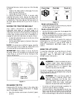
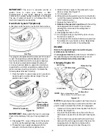
Push the oil drain valve in slightly, then rotate 
counterclockwise and pull outward to begin 
draining oil. See Figure 19.

Service the 

oil filter

 (if so equipped)


as instructed 

in the separate engine manual packed with your 
unit.

Perform the above steps in the opposite order after oil 
has finished draining. 

Refill the engine with new motor oil.

IMPORTANT:

 Refill the engine with the proper 

capacity and weight of motor oil as instructed in the 
separate engine manual.

Service 

air cleaner

 every 25 hours under normal 

conditions. Clean every few hours under extremely 
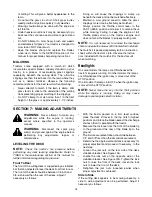
dusty condition. To service the air cleaner, refer to the 
separate engine manual packed with your unit.

The 

spark plug(s)

 should be cleaned and the gap reset 

once a season. Spark plug replacement is 
recommended at the start of each mowing season; 
check engine manual for correct plug type and gap 
specifications.

SECTION 9:  LUBRICATION

WARNING: 

Before lubricating, repairing,

or inspecting, always disengage PTO, move
shift lever into neutral position, set parking
brake, stop engine and remove key to prevent
unintended starting.

Engine

Lubricate the engine with motor oil as instructed in the
Engine


Owner’s Manual packed with your unit.

Pivot Points & Linkage

Lubricate all the pivot points on the drive system,
parking brake and lift linkage at least once a season
with light oil.

Transmission

The hydrostatic transmission is sealed at the factory.
Oil level cannot be checked nor can the oil be changed.

Front Wheels

Each of the front wheel axles is equipped with a grease
fitting. Lubricate with a grease gun after every 25 hours
of tractor operation.

Rear Wheels

The rear wheels should be removed from the axles
once a season. Lubricate the axles and the rims well
with an all-purpose grease before re-installing them.

SECTION 10:  SERVICE

TIRES

WARNING: 

Never exceed the maximum

inflation pressure shown on the sidewall of
the tire.

The recommended operating tire pressure is 10 psi for
the rear tires and 14 psi for the front tires. Refer to the
tire sidewall for exact tire manufacturer’s recommended
or maximum psi. Do not overinflate. Uneven tire
pressure could cause the cutting deck to mow
unevenly.

CUTTING BLADES

WARNING: 

Be sure to shut the engine off,

remove ignition key, disconnect the spark
plug wire(s) and ground against the engine to
prevent unintended starting before removing
the cutting blade(s) for sharpening or
replacement. Protect your hands by using
heavy gloves or a rag to grasp the cutting
blade.

WARNING: 

Periodically inspect the blade

adapter and/or spindle for cracks or damage,
especially if you strike a foreign object.
Replace immediately if damaged

.

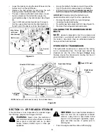
The blades may be removed as follows.

Remove the deck from beneath the tractor, (refer to
DECK REMOVAL) then gently flip the deck over to
expose its underside.

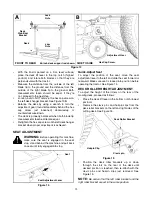
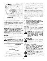
Place a block of wood between the center deck
housing baffle and the cutting blade to act as a
stabilizer. See Figure 20.

Use a 15/16" wrench to remove the hex flange nut
that secures the blade to the spindle assembly. See
Figure 20.

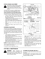
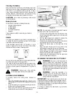
To properly sharpen the cutting blades, remove equal
amounts of metal from both ends of the blades along
the cutting edges, parallel to the trailing edge, at a 25°
to 30° angle. See Figure 21.

IMPORTANT:

 If the cutting edge of the blade has 

already been sharpened to within 5/8" of the wind wing 
radius, or if any metal separation is present, replace the 
blades with new ones. See Figure 21.

Summary of Contents for Hydrostatic Garden Tractor

Page 1: ...HE UNITED STATES IMPORTANT READ SAFETY RULES AND INSTRUCTIONS CAREFULLY Operator s Manual LES DISTRIBUTIONS RVI LIMITÉE 2955 JEAN BAPTISTE DESCHAMPS LACHINE QUEBEC H8T 1C5 Shown with optional bumper kit Hydrostatic Garden Tractor ...

Page 2: ...vice Please refer to the engine manufacturer s Owner s Operator s Manual packed separately with your unit for more information CALLING CUSTOMER SUPPORT If you have difficulty assembling this product or have any questions regarding the controls operation or maintenance of this unit please call your service dealer Please have your unit s model number and serial number ready when you call Content Pag...

Page 3: ...or 8 Always wear safety glasses or safety goggles during operation and while performing an adjustment or repair to protect your eyes Thrown objects which ricochet can cause serious injury to the eyes 9 Wear sturdy rough soled work shoes and close fitting slacks and shirts Loose fitting clothes and jewelry can be caught in movable parts Never operate this machine in bare feet or sandals 10 Be aware...

Page 4: ...heel weights or counterweights to improve stability 5 Use extra care with grass catchers or other attachments These can change the stability of the machine 6 Keep all movement on the slopes slow and gradual Do not make sudden changes in speed or direction Rapid engagement or braking could cause the front of the machine to lift and rapidly flip over backwards which could cause serious injury 7 Avoi...

Page 5: ...ank to no more than inch below bottom of filler neck to allow space for fuel expansion i Replace gasoline cap and tighten securely j If gasoline is spilled wipe it off the engine and equipment Move unit to another area Wait 5 minutes before starting the engine k To reduce fire hazards keep machine free of grass leaves or other debris build up Clean up oil or fuel spillage and remove any fuel soake...

Page 6: ...RESPONSIBILITY Restrict the use of this power machine to persons who read understand and follow the warnings and instructions in this manual and on the machine Safety Labels found on your unit SECTION 2 ATTACHMENTS ACCESSORIES The following attachments and accessories are compatible for your Garden Tractor See the retailer from which you purchased your tractor an Authorized Service Dealer 190 824 ...

Page 7: ...NE SLOPES WHERE YOU MAY NOT OPERATE SAFELY Do not mow on inclines with a slope in excess of 15 degrees a rise of approximately 2 1 2 feet every 10 feet A riding mower could overturn and cause serious injury If operating a walk behind mower on such a slope it is extremely difficult to maintain your footing and you could slip resulting in serious injury Operate RIDING mowers up and down slopes never...

Page 8: ... for shipping reasons use the following instructions to properly assemble the parts WARNING Do NOT operate the tractor without first attaching both the steering wheel AND the seat Doing so could result in serious injury to the operator NOTE There are two different styles of steering wheel cap See Figure 2 Styles vary by model Using your hands place the tractor s front tires in position for straigh...

Page 9: ...able of throwing objects Failure to operate the riding mower without the discharge cover in the proper operating position could result in serious personal injury and or property damage TIRE PRESSURE WARNING Maximum tire pressure under any circumstances is 30 p s i Equal tire pressure should be maintained at all times The tires on your unit may be over inflated for shipping purposes Reduce the tire...

Page 10: ...rd and align it with the hole on the rear of the left deck lift arm before releasing the pin to lock it in place as shown in Figure 5 Repeat on the right side INSTALLING THE PTO DECK BELT Make certain that the PTO Deck belt is routed around the spindle pulleys found beneath the belt guards and both idler pulleys as illustrated in inset in Figure 5 before proceeding Insert a 3 8 drive ratchet wrenc...

Page 11: ... PTO Power Take off Lever Models with manual PTO G Cruise Control Button PTO Power Take off Knob Models with electric PTO H Ignition Switch B Systems Indicator Monitor Hour Meter I Brake Pedal C Choke Control J Drive Pedal D Cup Holder K Cargo Net Not Shown E Throttle Control Lever L Deck Lift Lever F Parking Brake Button M Seat Adjustment Lever H E A C G F D K J I L NOTE Steering Wheel not shown ...

Page 12: ...our application IGNITION SWITCH WARNING Never leave a running machine unattended Always disengage PTO move shift lever into neutral position set parking brake stop engine and remove key to prevent unintended starting To start the engine insert the key into the ignition switch and turn clockwise to the START position Release the key into the NORMAL MOWING MODE position once the engine has fired To ...

Page 13: ...attachments pull outward on the PTO knob or move the PTO lever to ON position as the case may be Push the PTO knob inward or move the PTO lever to BLade Stop position to disengage power to the cutting deck NOTE The PTO knob lever must be in the Blade Stop position when starting the engine when traveling in reverse and if the operator leaves the seat SEAT ADJUSTMENT LEVER To adjust the seat forward...

Page 14: ...ver is in the disengaged OFF position The engine will automatically shut off if the operator leaves the seat before engaging the parking brake Models with Manual PTO Blade Engage The engine will automatically shut off if the operator leaves the tractor s seat with the PTO Blade Engage lever in the engaged ON position regardless of whether the parking brake is engaged With the ignition key in the N...

Page 15: ...ward Models with Manual PTO ONLY SETTING THE CUTTING HEIGHT Select the height position of the cutting deck by placing the deck lift lever in any of the six different cutting height notches on the right side of the fender Then adjust the deck wheels so that they are between inch and inch above the ground when the tractor is on a smooth flat surface such as a driveway Figure 9 WARNING Keep hands and...

Page 16: ... drive pedal with the ball of your foot NOT your heel until the desired speed is achieved See Figure 10 IMPORTANT Do NOT attempt to change the direction of travel when the tractor is in motion Always bring the tractor to a complete stop before pivoting the drive pedal from forward to reverse or vice versa Figure 10 DRIVING ON SLOPES Refer to the SLOPE GAUGE on page 7 to help determine slopes where...

Page 17: ...Models with manual PTO Grasp the PTO lever and pivot it all the way forward into the engaged ON position Models with electric PTO Pull the PTO knob outward into the engaged ON position See Figure 12 Keep the throttle lever in the FAST rabbit position for the most efficient use of the cutting deck or other separately available attachments IMPORTANT The engine or electric PTO clutch will automatical...

Page 18: ...dlights On some models the lamps are ON whenever the tractor s engine is running On other models the lamps are ON whenever the ignition key is moved out of the STOP position On all models the lamps turn OFF when the ignition key is moved to the STOP position NOTE Never move the key into the Start position while the engine is running Doing so may cause damage to your engine s electric starter SECTI...

Page 19: ...stop stand behind the machine and pull back on seat until fully engaged into stop Figure 14 Quick Adjust Seat To adjust the position of the seat move the seat adjustment lever to the left and slide the seat forward or rearward Make sure seat is locked into position before operating the tractor See Figure 14 DECK ROLLER HEIGHT ADJUSTMENT To adjust the height of the rollers on the rear of the mowing...

Page 20: ...ck washer on the top of ball joint See Figure 17 Thread the ball joint toward the jam nut to shorten the drag link Thread the ball joint away from the jam nut to lengthen the drag link Replace hex nut and lock washer and retighten the jam nut after proper adjustment is achieved NOTE Threading the ball joints too far onto the drag links will cause the front tires to toe in too far Proper toe in is ...

Page 21: ...engine and place the throttle lever in the FAST rabbit position 7 Engage the tractor s PTO 8 Remain in the operator s position with the cutting deck engaged for a minimum of two minutes allowing the underside of the cutting deck to throughly rinse 9 Disengage the tractor s PTO 10 Turn the ignition key to the STOP position to turn the tractor s engine off 11 Turn the water off and detach the hose c...

Page 22: ...peration Rear Wheels The rear wheels should be removed from the axles once a season Lubricate the axles and the rims well with an all purpose grease before re installing them SECTION 10 SERVICE TIRES WARNING Never exceed the maximum inflation pressure shown on the sidewall of the tire The recommended operating tire pressure is 10 psi for the rear tires and 14 psi for the front tires Refer to the t...

Page 23: ...ire Be certain that the wires are connected to the correct terminals reversing them could change the polarity and cause damage to your engine s alternating system IMPORTANT 1 Battery wires must be connected to the correct terminals Reversing them could change the polarity and damage engine s alternating system 2 Do not jump start a damaged battery 3 When storing the battery disconnect the negative...

Page 24: ...notch on the right fender Remove the PTO belt from around the electric PTO clutch and from around the PTO idler pulley s Figure 23 NOTE The deck belt on the deck does NOT need to be removed in order to remove the deck Looking at the cutting deck from the left side of the tractor locate the deck support pin on the rear left side of the deck Pull the deck support pin outward to release the deck from...

Page 25: ...ed and special tools i e air impact wrench in order to change the tractor s drive belts See an authorized dealer to have your drive belts replaced HYDROSTATIC TRANSMISSION The hydrostatic transmission is sealed at the factory and is maintenance free The fluid level cannot be checked nor can the oil be changed Always keep thearea around the transmission cooling fan free of grass and debris at all t...

Page 26: ...ttle in FAST position Engine runs erratic Unit running with CHOKE applied Spark plug wire loose Blocked fuel line or stale fuel Vent in gas cap plugged Water or dirt in fuel system Dirty air cleaner Place throttle lever in FAST position Connect and tighten spark plug wire Clean fuel line fill tank with clean fresh less than 30 days old gasoline Replace fuel filter if so equipped Clear vent or repl...

Page 27: ...ers are considered consumable items and as such are not warranted NOTE Regular maintenance replacement parts and related inspections and adjustments are excluded from coverage when made as part of normal maintenance service TRACTOR ATTACHMENT WARRANTY Mower decks included with your product or sold separately as an attachment for your garden tractors will be warranted according to the above terms o...

Reviews: