background image

Service

7

12

Replacing Belt

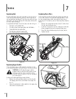
Remove the belt cover by removing five hex screws. See Fig. 8-1. 

Then simply pull the belt off by grasping it from the bottom of 

the auger pulley and pulling off.  Once you remove the belt from 

the pulleys, you can push down on the idler pulley to release the 

belt from under belt keeper.
To replace the belt follow these instructions and refer to Fig. 8-2:

Push down on the Idler pulley.

1. 

Put belt on top of the auger pulley under belt keeper.

2. 

Thread belt around engine pulley.

3. 

Push belt over bottom of auger pulley.

4. 

Reinstall the belt cover removed earlier.

5. 

Replacing Auger Paddles

The snow thrower auger’s rubber paddles are subject to wear 

and should be replaced if any signs of excessive wear are present.

CAUTION: 

Do NOT allow the auger’s rubber 

paddles to wear to the point where portions of the 

metal auger itself can come in contact with the 

pavement. Doing so can result in serious damage to 

your snow thrower.

To change the rubber paddles, proceed as follows:

Remove the existing rubber paddles by unthreading the 

1. 

self-tapping screws which secure them to the auger. See 
Fig. 8-3.
Secure the replacement rubber paddles to the auger using 

2. 

the hardware removed earlier. 

Replacing Shave Plate 

The shave plate is attached to the bottom of the auger housing 

and is subject to wear. It should be checked periodically. There 

are two wearing edges and the shave plate can be reversed. 

Refer to Fig. 8-3. To replace or reverse the shave plate proceed as 

follows:

Remove the carriage bolts and hex lock nuts which attach 

1. 

it to the snow thrower housing.
Install new shave plate (or reverse), making sure the heads 

2. 

of the carriage bolts are on the inside of the housing.
Adjust the shave plate according to instructions above

3. 

Tighten securely.

4. 

Idler Pulley

Belt Keeper

Hex Screws

Figure 8-1

Figure 8-2

Engine Pulley

Auger Pulley

1

4

3

2

Self-Tapping Screws

Figure 8-3

Summary of Contents for Single-Stage

Page 1: ...OW ALL SAFETY RULES AND INSTRUCTIONS IN THIS MANUAL BEFORE ATTEMPTING TO OPERATE THIS MACHINE FAILURE TO COMPLY WITH THESE INSTRUCTIONS MAY RESULT IN PERSONAL INJURY LES DISTRIBUTIONS RVI LIMITÉE 2955 JEAN BAPTISTE DESCHAMPS LACHINE QUEBEC H8T 1C5 MTD LLC P O BOX 361131 CLEVELAND OHIO 44136 0019 769 06199 06 09 10 Single Stage Snow Throwers ...

Page 2: ... available at the time of printing Review this manual frequently to familiarize yourself with the machine its features and operation Please be aware that this Operator s Manual may cover a range of product specifications for various models Characteristics and features discussed and or illustrated in this manual may not be applicable to all models The manufacturer reserves the right to change produ...

Page 3: ...ochet can cause serious injury to the eyes Do not operate without wearing adequate winter outer 2 garments Do not wear jewelry long scarves or other loose clothing which could become entangled in moving parts Wear footwear which will improve footing on slippery surfaces Use a grounded three wire extension cord and receptacle 3 for all machines with electric start engines Disengage all control leve...

Page 4: ...embly 4 Keep all safety devices in place and working Never run an engine indoors or in a poorly ventilated area 5 Engine exhaust contains carbon monoxide an odorless and deadly gas Do not operate machine while under the influence of 6 alcohol or drugs Muffler and engine become hot and can cause a burn Do 7 not touch Keep children away Exercise extreme caution when operating on or crossing 8 gravel...

Page 5: ...ere 10 there is an open flame spark or pilot light such as a water heater furnace clothes dryer etc Always refer to the operator s manual for proper 11 instructions on off season storage Check fuel line tank cap and fittings frequently for cracks 12 or leaks Replace if necessary Do not crank engine with spark plug removed 13 According to the Consumer Products Safety Commission 14 CPSC and the U S ...

Page 6: ... near rotating parts in the auger impeller housing or chute assembly Contact with the rotating parts can amputate hands and feet WARNING THROWN OBJECTS This machine may pick up and throw and objects which can cause serious personal injury WARNING GASOLINE IS FLAMMABLE Allow the engine to cool at least two minutes before refueling WARNING CARBON MONOXIDE Never run an engine indoors or in a poorly v...

Page 7: ...erating position Make sure not to pinch or crimp the cable Tighten the wing knobs See Figure 3 2 3 Set Up Adding Fuel Refer to the Engine Operator s Manual packed with your snow thrower for information on adding fuel Adding Oil Refer to the Engine Operator s Manual packed with your snow thrower for information on adding and checking oil Adjustments Chute Assembly The pitch of the chute assembly co...

Page 8: ...control against the upper handle to engage the auger release it to disengage Chute Assembly Rotate the discharge chute to the left or right using chute handle The angle of the discharge chute controls the distance that the snow is thrown Tilt the discharge chute up for greater distance tilt down for less distance Loosen the hand knob on the side of the discharge chute to adjust Tilt the chute to t...

Page 9: ...ndle will raise the auger off the ground and stop the forward motion NOTE Excessive upward pressure on the handle will result in premature wear on the rubber auger blades which are not be covered by the warranty Clearing a Clogged Discharge Chute WARNING Never use your hands to clear a clogged chute assembly Shut off engine and remain behind handles until all moving parts have stopped before using...

Page 10: ...s to see if it is difficult to pull If the starter is difficult to pull remove the spark plug and 4 pull the handle several times to ensure that any oil trapped in the head is removed Caution Oil may come out of the spark plug hole when it is removed and the starter handle is pulled Inspect the spark plug If it is wet clean off any oil before 5 re installing Control Cable As a result of both the c...

Page 11: ...lean dry area 1 If storing the snow thrower in an unventilated area 2 rustproof the machine using a light oil or silicone to coat the snow thrower Clean the exterior of the engine and the snow thrower 3 Lubricate pivot points on control handle and extension 4 spring at end of control cable with a light oil Refer to engine manual for correct engine storage 5 instructions ...

Page 12: ...self can come in contact with the pavement Doing so can result in serious damage to your snow thrower To change the rubber paddles proceed as follows Remove the existing rubber paddles by unthreading the 1 self tapping screws which secure them to the auger See Fig 8 3 Secure the replacement rubber paddles to the auger using 2 the hardware removed earlier Replacing Shave Plate The shave plate is at...

Page 13: ...uger drive belt loose or damaged 2 Adjust auger control cable as shown in 1 Maintenance Adjustments section Replace auger drive belt 2 Augers continue to rotate Auger control cable out of adjustment 1 Adjust auger control cable as shown in 1 Maintenance Adjustments section Unit fails to discharge snow Chute assembly clogged 1 Foreign object lodged in auger 2 Auger control cable out of adjustment 3...

Page 14: ...oads are also available free of charge at www mtdproducts com Component Part Number and Description 731 1033 Shave Plate 954 0101A Belt V Type 2M1 Models 954 04204 Belt V Type 2N1 2P5 Models 735 04032 Spiral Crescent 735 04033 Rubber Paddle 753 04472 Replacement Kit includes 4 crescents 2 paddles and hardware 731 05632 Key 746 04237 Clutch Cable 951 10292 Spark Plug ...

Page 15: ...as lubricants filters blade sharpening tune ups brake adjustments clutch adjustments deck adjustments and normal deterioration of the exterior finish due to use or exposure d Service completed by someone other than an authorized service dealer e MTD does not extend any warranty for products sold or exported outside of Canada including possessions and territories f Replacement parts that are not ge...

Page 16: ...E RESPECTIVE MANUFACTURERS SERVICE DEALERS Belts light bulbs clutch parts friction wheels grass bags tires seats rider deck wheels and cutting blades are covered by a 60 day limited warranty Batteries are warranted against defect for 90 days at 100 of their value and 50 of their value for the period between the 91st day and the 120th day Fuses shear bolts and blade adapters are considered consumab...

Reviews: