24
©
2019
Columbus McKinnon Industrial Products GmbH
(View from the motor side)
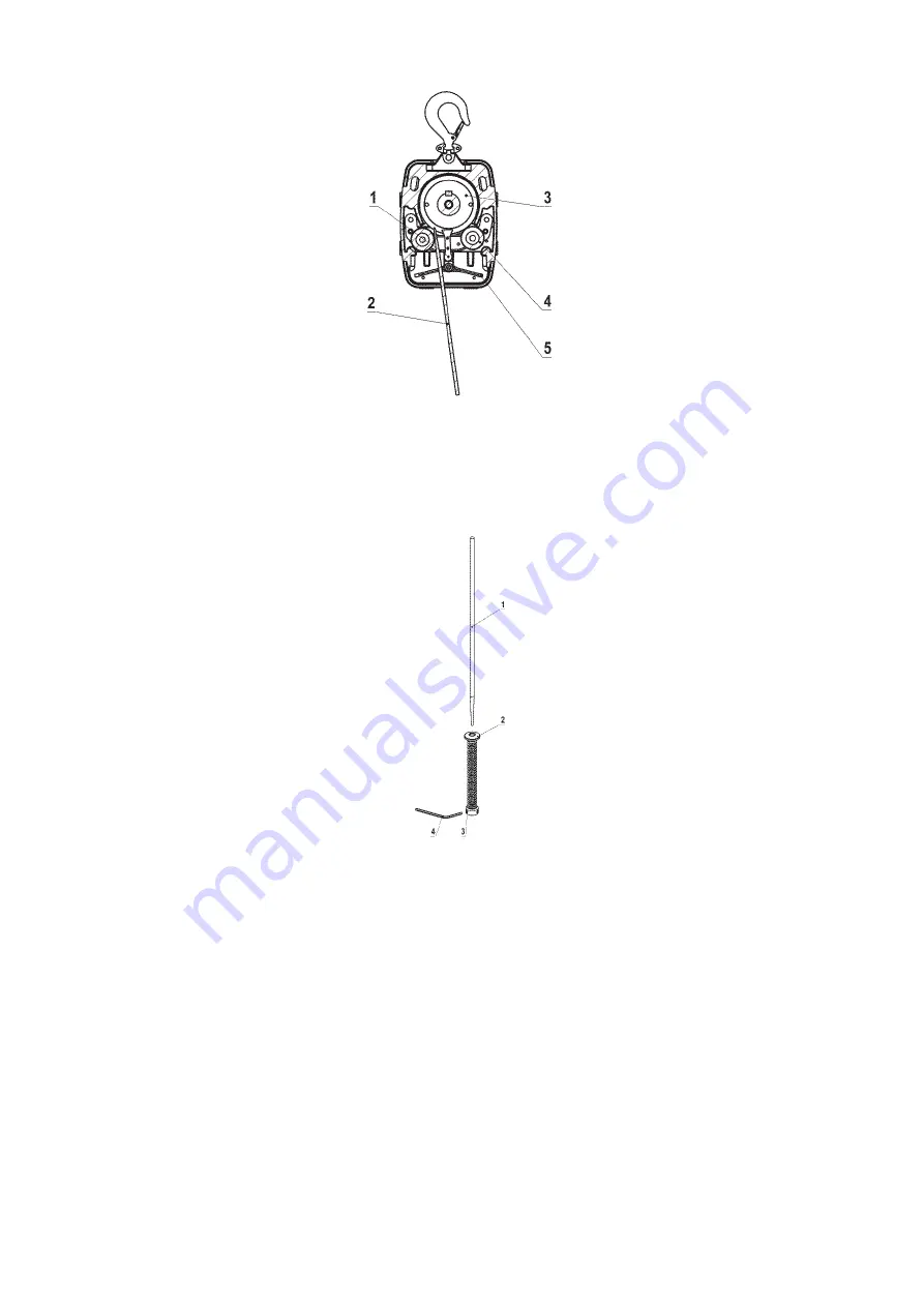
Mounting spring-kit for limit switches
Slide supporting rope (1) through the spring-kit (pos. 2+3) until the rope protrudes app. 5 cm over the opposite side. Then screw the two
threaded pins with an SW 3 Allen key until the roped is jammed (torque approx. 3 Nm).
Modification of 1-strand to 2-strand version (optional)
Install support hook (1) and suspension bar (3) with suspension bolt (14) and retaining ring (2).
Then install suspension bar on the main unit with suspension bolts (5) and roll pin (4). Slide support rope with the tip of the cable
through the spring-kit (6) and then through the guide pulley (9). Then mount the wedge end clamp (11) onto the end of the cable as
described. Secure wedge end clamp (11) with pin (12) and split pin (13) on the suspension bar (3). The threaded pins of the shock-
absorbing spring-kit (6) are not tightened or installed here.
The shock-absorbing spring-kit (7) is installed as normal on the other end of the support rope with the threaded pins.
www.hoistandwinch.co.uk


