background image

ALARM SCREEN

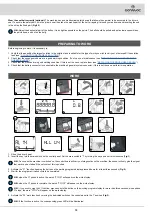
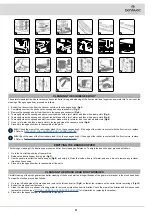
If there is an error, the writing AL is shown on the control display followed by a number (

Fig.17

), this stays visible until the error is resolved. When 

an error occurs, do as follows:

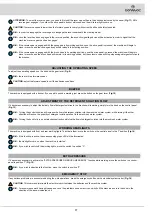
1.  Stop the machine immediately.

2. 

If the error persists, switch off the machine, wait for at least ten seconds and switch on the machine.

3.  If the error persists contact the nearest service centre.

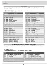
ALARM NUMBER

DESCRIPTION

AL_1: General

Memory error

AL_2: General

Key fault

AL_3: General

Undervoltage

AL_4: General

Overvoltage

AL_5: General

Batt. connection

AL_6: General

Dashboard communication

AL_7: General

FFM communication

AL_8: General

Internal communication 1

AL_9: General

Internal communication 2

AL_10: General

Enter tag

AL_11: General

Invalid tag

AL_12: General

Update in progress…

AL_13: General

Switch-off

AL_14: General

Recovery tank full 

AL_15: General

Brake fluid Reserve

AL_41:  Function   Overtemperature
AL_42: Function Power board damaged
AL_43: Function Main fuse faulty
AL_44: Function Main contactor faulty 
AL_45: Function Main contactor faulty - CC
AL_46: Function Overcurrent - brush outputs 1-2-3
AL_47: Function Overcurrent - vacuum cleaner outputs 1-2
AL_48: Function Overcurrent - water pump outputs
AL_49: Function Amperometric - brush output 1
AL_50: Function Amperometric - brush output 2
AL_51: Function Amperometric - brush output 3

ALARM NUMBER

DESCRIPTION

AL_52: Function Amperometric - vacuum cleaner output 1
AL_53: Function Amperometric - vacuum cleaner output 2
AL_60: Function Time-out  Actuator 1
AL_61: Function Amperometric  Actuator 1
AL_62: Function Overcurrent  Actuator 1
AL_63: Function Incorrect limit switches - actuator 1
AL_64: Function Time-out  Actuator 2
AL_65: Function Amperometric  Actuator 2
AL_66: Function Overcurrent  Actuator 2
AL_67: Function Incorrect limit switches - actuator 2
AL_68: Function Time-out  Actuator 3
AL_69: Function Amperometric  Actuator 3
AL_70: Traction

Overcurrent  Actuator 3

AL_71: Traction

Incorrect limit switches - actuator 3

AL_80: Traction

Overtemperature

AL_81: Traction

Power board damaged

AL_82: Traction

Main fuse faulty

AL_83: Traction

Main contactor faulty 

AL_84: Traction

Main contactor faulty - CC

AL_85: Traction

Overcurrent - traction output

AL_86: Traction

Amperometric - traction output

AL_87: Traction

Motor reading

AL_88: Traction

Electric brake fault

AL_89: Traction

Pedal fault

AL_90: Traction

Pedal pressed

AL_91: Traction

Encoder fault

DETERGENT SOLUTION RECYCLING SYSTEM ALARM SCREEN

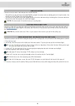
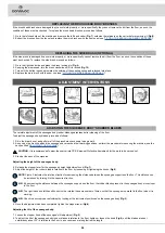
If there is an error, the letters "AL" will appear on the work program display followed by a number (

Fig.18

); it will remain visible until the error has 

been resolved.

When an error occurs, do as follows:

1.  Stop the machine immediately.

2. 

If the error persists, switch off the machine, wait for at least ten seconds and switch on the machine.

3.  If the error persists contact the nearest service centre.

ALARM 

NUMBER

DESCRIPTION

ALL t1

Recovery tank empty, or tank float or membrane

ALL t2

Membrane settling tank empty

ALL t3

Solution tank empty

ALL 04

Membrane filter clogged

ALL 06

Recovery tank pump blocked

ALL 07

ELV1 solenoid valve blocked

ALL 08

ELV2 solenoid valve blocked

ALARM 

NUMBER

DESCRIPTION

ALL 09

Activation of phase F1 with phase F2 active

ALL 10

Problem with reserve solution tank float

ALL 11

Problem with solution tank minimum level float

ALL 12

Problem with solution tank maximum level float

ALL 13

Problem with solution tank floats

ALL 14

Problem with tank float or membrane or pump P2

18

Summary of Contents for C85 2018 BS NSC BASIC

Page 1: ...SCRUBBING MACHINES ORIGINAL INSTRUCTIONS DOC 10099175 Ver AA 08 2020 USE AND MAINTENANCE MANUAL ...

Page 2: ......

Page 3: ... 11 HOW TO UNPACK THE MACHINE 11 HOW TO MOVE THE MACHINE 11 MACHINE SAFETY 11 PREPARATION OF MACHINE 12 TYPE OF BATTERY TO BE USED 12 BATTERY MAINTENANCE AND DISPOSAL 12 INSERTING THE BATTERIES IN THE MACHINE 12 RECHARGING THE BATTERIES 12 FILLING WITH DETERGENT SOLUTION 13 INSERTING WATER SYSTEM FILTER 13 ASSEMBLING THE BRUSH HEAD BODY BRUSHES 14 FITTING THE SIDE BRUSH OPTIONAL 14 USER SEAT ADJUS...

Page 4: ... BRUSH OPTIONAL 22 DRAINING THE RECOVERY TANK 22 EMPTYING THE SOLUTION TANK 22 EMPTYING THE MEMBRANE SETTLING TANK 22 EMPTYING THE DEGREASER SETTLING TANK 22 CLEANING THE WATER SYSTEM FILTER 23 CLEANING THE VACUUM TUBE 23 EXTRAORDINARY MAINTENANCE WORK 23 REPLACING THE SQUEEGEE BODY RUBBER BLADES 23 REPLACING THE BRUSH HEAD BODY BRUSHES 24 REPLACING THE SIDE BRUSH OPTIONAL 24 ADJUSTMENT INTERVENTI...

Page 5: ... caused by corrosive substances Danger symbol battery acid leakage Indicates the danger of leaking acid or acid fumes from the batteries while they are being recharged Danger symbol moving carriages Indicates that the packed product should be handled with suitable carriages that conform to legal requirements Mandatory room ventilation symbol Informs the operator that the room must be ventilated wh...

Page 6: ...0 Buzzer button 11 Forward speed selector knob 12 Main key switch 13 Tank cover support 14 Recovery tank filling quick connector 15 Recovery tank cover 16 Settling tank cover 17 Rear panel 18 Settling tank drainage tube degreaser 19 Recovery tank drainage tube 20 Settling tank drainage tube membrane 21 Solution tank drain hose 22 Brake pedal 23 Drive pedal 24 Detergent solution flow adjustment lev...

Page 7: ...is not liable for damages resulting from failure to comply with this veto STORING THE USE AND MAINTENANCE MANUAL The Use and Maintenance Manual must be stored in its special pouch close to the machine protected from liquids and anything else that could compromise its legibility ON CONSIGNMENT OF THE MACHINE When the machine is consigned to the customer an immediate check must be performed to ensur...

Page 8: ...he control panel positioned on the front of the machine to indicate the main switch Acoustic signalling device control label Applied in the vicinity of the steering column to indicate the acoustic signalling device s control button Label for detergent solution tap command Applied in the vicinity of the control column to identify the detergent solution tap s control lever Label indicating the need ...

Page 9: ... explain how to correctly position the sensor which enables machine speed around corners to be reduced SERIAL NUMBER PLATE The serial number plate is located at the rear of the steering column and indicates the machine s general characteristics including its serial number The serial number is a very important piece of information and should always be provided together with any request for assistan...

Page 10: ...e central brush head kg 45 45 Lateral brush head brush Ø external bristles mm Ø290 Ø290 Electrical characteristics of the side brush head motor V W 36 200 36 200 Rotations of single lateral brush head brush rpm 140 140 Maximum weight exerted by the lateral brush head kg 20 20 Traction motor electrical properties voltage power V W 36 1200 36 1200 Maximum slope during work GVW 10 10 Maximum working ...

Page 11: ... people or objects near the machine HOW TO MOVE THE MACHINE To transport the machine safely proceed as follows 1 Check that all the machine tanks are empty if this is not the case empty them see EMPTYING THE RECOVERY TANK and also EMPTYING THE SOLUTION TANK and EMPTYING THE MEMBRANE SETTLING TANK and EMPTYING THE DEGREASER SETTLING TANK 2 Place the machine on the transport vehicle WARNING secure t...

Page 12: ...onsibility for any damage to property or injury persons in the event that the batteries are replaced by an unauthorized technician RECHARGING THE BATTERIES The batteries must be charged prior to the first use and when they don t provide enough power for tasks that could formerly be performed without difficulty ATTENTION to avoid any permanent damage to the batteries it is essential to avoid their ...

Page 13: ...this is not the case close it Fig 7 8 Turn the tank cover into the maintenance position using the support to prevent it from rotating Fig 8 9 Remove the recovery tank cover Fig 9 10 Add the liquid detergent to the tank in the concentration and manner indicated on the detergent manufacturer s label use the minimum amount of detergent recommended CAUTION it is recommended to wear the appropriate PPE...

Page 14: ... at 90 Use the lever on the left side of the seat Fig 19 to adjust the backrest of the seat Driving position adjustment The seat should always be positioned using the pedals as a reference Use the lever in the lower part of the seat Fig 20 to adjust the seat N B The distance should be adjusted so that with the pedals fully pressed to the floor the knees are slightly bent about 120 N B Adjust the d...

Page 15: ...or is connected to the machine s general system connector if this is not the case perform this operation WORK 1 Sit on the driver s seat 2 Insert the key into the main switch on the control panel Set the main switch to I by turning the key a quarter turn clockwise Fig 1 N B As soon as the machine is switched on the control board will carry out diagnostics on the machine the buzzer will only give t...

Page 16: ... on ramps and slippery surfaces and carry out the scrubbing operation by moving the machine upwards rather than downwards ATTENTION Do not use the machine in areas where the ambient temperature is higher than 43 C 110 F Do not use the scrubbing functions in areas where the ambient temperature is less than freezing 0 C 32 F GENERAL HOUR METER The command display is located on the control panel and ...

Page 17: ...ton on the gear lever Fig 12 ADJUSTMENT OF THE DETERGENT SOLUTION FLOW If it becomes necessary to adjust the delivery flow of detergent solution to the brushes while working simply turn the knob on the control panel Fig 13 N B Turning the knob clockwise will increase the flow of detergent solution into the machine s water system while turning it the other direction will reduce the quantity of dete...

Page 18: ...ctuator 1 AL_64 Function Time out Actuator 2 AL_65 Function Amperometric Actuator 2 AL_66 Function Overcurrent Actuator 2 AL_67 Function Incorrect limit switches actuator 2 AL_68 Function Time out Actuator 3 AL_69 Function Amperometric Actuator 3 AL_70 Traction Overcurrent Actuator 3 AL_71 Traction Incorrect limit switches actuator 3 AL_80 Traction Overtemperature AL_81 Traction Power board damage...

Page 19: ...DETERGENT SOLUTION RECYCLING The machine can also be moved without activating the detergent solution recycling function to use the machine in the following manner you must 1 Sit on the driver s seat 2 Insert the key into the main switch on the control panel Set the main switch to I by turning the key a quarter turn clockwise Fig 1 N B As soon as the machine is switched on the control board will ca...

Page 20: ...Debris hopper Empty the debris hopper and clean inside see EMPTYING THE DEBRIS HOPPER Brush head brushes Clean the brushes see CLEANING THE BRUSH HEAD BRUSHES Recovery tank basket filter Clean the recovery tank basket filter see EMPTYING THE RECOVERY TANK WEEKLY BEFORE A LONG PERIOD OF INACTIVITY Recovery tank Every working week empty the recovery tank see EMPTYING THE RECOVERY TANK Solution tank ...

Page 21: ...if the edge of the rubber in contact with the floor is worn replace it Refer to REPLACING THE SQUEEGEE BODY RUBBER BLADES EMPTYING THE DEBRIS HOPPER The thorough cleaning of the debris hopper ensures better floor cleaning performance To empty the debris hopper proceed as follows 1 Go to the front left hand side of the machine 2 Release the debris hopper locking pin Fig 7 3 Use the handle to extrac...

Page 22: ...ank must be emptied Proceed as follows to empty the membrane settling tank 1 Stand at the back of the machine and open the rear panel 2 Turn the tank cover into the maintenance position using the support to prevent it from rotating Fig 13 3 Remove the settling tank cover Fig 17 4 Remove the membrane settling tank drainage tube Fig 19 from the stop and bend the end of the drainage tube so as to cre...

Page 23: ...e the machine to the maintenance area NOTE the place designated for this operation must comply with current environmental protection regulations 2 Make sure the machine is in a safe condition see MACHINE SAFETY MEASURES CAUTION it is recommended to wear the appropriate PPE Personal Protective Equipment for the work to be carried out REPLACING THE SQUEEGEE BODY RUBBER BLADES Ensuring the integrity ...

Page 24: ...ng at the instrument positioned on the squeegee body Fig 3 6 Once the adjustment has been completed tighten the stopper lever Fig 4 Adjusting the tilt of the squeegee body 7 Loosen the stopper knob of the squeegee s tilt adjustment Fig 5 8 To adjust the tilt of the squeegee body rubber blades in relation to the floor tighten or loosen the knob Fig 6 until the blades are bent outwards by about 30 i...

Page 25: ...CYLINDRICAL BRUSH 1 449931 NATURAL ø210x810 REAR CYLINDRICAL BRUSH 1 427709 PPL ø0 3 ø290 DISC BRUSH BLUE COLOUR 1 427710 PPL ø0 6 ø290 DISC BRUSH WHITE COLOUR 1 427711 PPL ø0 9 ø290 DISC BRUSH BLACK COLOUR 1 427712 ABRASIVE ø290 DISC BRUSH 1 449920 NATURAL ø290 DISC BRUSH 1 447713 ø290 PAD HOLDER CHOOSING AND USING BRUSHES POLYPROPYLENE BRUSH PPL Used on all types of floors Good resistance to wea...

Page 26: ...he recovery tank cover is not closed correctly Tighten the hinges on the side of the recovery tank or check that there are no obstructions that prevent these from tightening The vacuum motor does not start Recovery tank full Empty the recovery tank read the paragraph EMPTYING THE RECOVERY TANK Recovery tank full of foam Empty the recovery tank read the paragraph EMPTYING THE RECOVERY TANK Use less...

Page 27: ...ves 2006 42 EC Machinery Directive 2014 30 EU Electromagnetic compatibility directive They also comply with the following standards EN 60335 1 2012 A11 2014 EN 60335 2 72 2012 EN 12100 2010 EN 61000 6 2 2005 AC 2005 EN 61000 6 3 2007 A1 2011 AC 2012 EN 62233 2008 AC 2008 The person authorized to compile the technical file Mr Giancarlo Ruffo Via Maestri del Lavoro 13 37059 Santa Maria di Zevio VR I...

Page 28: ...28 ...

Page 29: ...29 ...

Page 30: ...30 ...

Page 31: ......

Page 32: ...A Via Maestri del Lavoro 13 37059 Santa Maria di Zevio Verona ITALY Tel 045 8774222 Fax 045 8750303 www comac it com comac it Organization certified with Q C B Italia ISO 9001 2008 ISO 14001 2015 OHSAS 18001 2007 ...

Reviews: