background image


9

GENERAL SAFETY REGULATIONS 

 
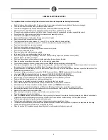
The regulations below must be carefully followed in order to avoid harm to the operator and damage to the machine. 


Read the labels on the machine carefully. Do not cover them for any reason and replace them immediately if they become damaged. 


The machine must be exclusively used by authorised, trained personnel. 


The machine is designed for dry use only and should not be used or kept outdoors in damp conditions. 


Disconnect from the mains/battery before performing cleaning or maintenance operations on the machine. 


If the machine is used where there is a risk of falling objects, the machine must be equipped with protections against falling objects. 


During the working of the machine, pay attention to other people and especially to children. 


The machine is not suitable for cleaning carpets. 


Do not mix different types of detergent as this may produce harmful gases. 


Do not place any liquid containers on the machine. 


The storage temperature must be between -25

C and +55

C; do not store outdoors in damp conditions. 


Conditions of use: room temperature between 0°C and 40°C with relative humidity between 30 and 95% 


Do not use the machine in an explosive atmosphere. 


Do not use the machine as a means of transport. 


Do not use acid solutions that could damage the machine and/or harm people. 


Do not vacuum inflammable liquids. 


Do not use the device to collect dangerous powders. 


In the event of a fire, use a powder extinguisher. Do not use water. 


Do not knock against shelving or scaffolding, where there is a danger of falling objects. Use protective devices (helmet). 


Adapt the speed to the adhesion conditions. 


Do not use the machine on surfaces with an inclination greater than the one shown on the plate. 


When the machine is in parking mode, remove the key and insert the parking brake. 


If you notice any damage to the battery charger cable, contact a COMAC technical assistance centre immediately. 


The machine is designed to carry out the washing and drying operations simultaneously. Different operations should only be carried out in areas where 
the passage of unauthorised persons is prohibited. Signal the presence of damp floors with suitable signs. 


If the machine does not work properly, check this is not caused by failure to carry out routine maintenance. Otherwise, request the intervention of the 
COMAC technical assistance centre. 


If you need to replace any components, request the ORIGINAL spare parts from a COMAC dealer and/or Authorised Retailer. 


Use original COMAC brushes only indicated in the paragraph “CHOOSING AND USING THE BRUSHES". 


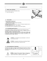
In the event of danger, activate the emergency lever (connector placed under the operator's seat) immediately. 


Before carrying out any maintenance work, switch off the machine and disconnect the battery connector. 


Restore all electrical connections after any maintenance interventions. 


Do not remove any protection devices which require the use of tools in order to be removed. 


Do not wash the machine with direct water jets or with pressurised water, nor with corrosive substances. 


After at least every 200 hours of operation, have the machine checked by a COMAC assistance centre 


To prevent scaling in the solution tank filter, do not fill the tank with detergent solution many hours before using the machine. 


Before using the machine, check that all the hatches and covers are positioned as shown in this Use and Maintenance Manual. 


Make sure the recovery tank is empty before lifting. 


When disposing of consumption materials, observe the laws and regulations in force. 


The machine does not cause harmful vibrations. 


When your COMAC machine has reached the end of its long working life, dispose of the materials it contains (especially oils, batteries and electronic 
components) in an appropriate manner, and bearing in mind that the machine itself was constructed using 100% recyclable materials. 


The batteries must be removed from the machine before its disposal. 


The batteries must be disposed of in a safe manner, fully observing the laws and regulations in force. 


The machine is not suitable for use by children and persons with reduced physical, mental and sensory capabilities, or people who lack experience and knowledge. 


Children must be supervised to ensure they do not play with the device. 


When the machine if left unattended, engage the parking brake for safety against unintentional movements. 

Summary of Contents for INNOVA 2011

Page 1: ...USE AND MAINTENANCE MANUAL INNOVA 2011 60 65 75 85 B 70 S ED 06 2012 EN ORIGINAL INSTRUCTIONS Doc 10029401 Ver AB...

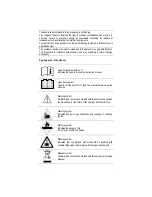
Page 2: ...ign and supply Symbols used in the manual Open book symbol with an i Indicates the need to consult the instruction manual Open book symbol Used to tell the operator to read the manual before using the...

Page 3: ...CTION VERSIONS WITH CB 15 19 BATTERY CHARGE LEVEL INDICATOR 17 20 WORKING FORWARD SPEED 17 21 REVERSE FUNCTION 17 22 RECOVERY TANK 17 23 SOLUTION TANK INNOVA 2011 60 65 75 85 B 17 24 SOLUTION TANK 70S...

Page 4: ...OF THE DETERGENT CANISTER VERSIONS WITH CDS 35 EXTRAORDINARY MAINTENANCE 36 60 REPLACING THE FRONT SQUEEGEE RUBBER 36 61 REPLACING THE REAR SQUEEGEE RUBBER 36 62 REPLACEMENT OF THE BRUSH HEAD CASING 3...

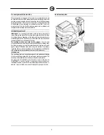
Page 5: ...irt removed and the detergent solution not absorbed by the floor The machine must be only used for this purpose Even the best machines will only work well if used correctly and kept in good working or...

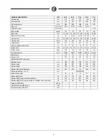
Page 6: ...4 310 24 310 24 310 24 310 Suction vacuum mbar 160 160 160 160 160 Rear elastic wheels mm 300x70 300x70 300x70 300x70 300x70 Solution tank l 110 110 110 110 110 Recovery tank l 125 125 125 125 125 Det...

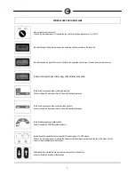
Page 7: ...on symbol idle position Used to indicate the movement levers of the brush head and squeegee Brush head squeegee motion symbol working position Used to indicate the movement levers of the brush head an...

Page 8: ...d to indicate the pedal to increase the pressure on the brushes Indicates the maximum gradient Parking brake symbol Used on the instrument panel to indicate the red warning light showing parking brake...

Page 9: ...of unauthorised persons is prohibited Signal the presence of damp floors with suitable signs If the machine does not work properly check this is not caused by failure to carry out routine maintenance...

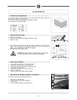
Page 10: ...the squeegee read the ASSEMBLING THE SQUEEGEE paragraph 5 Keep the pallet for any future transport needs ATTENTION if the product is delivered in cardboard containers handle the packed product with s...

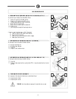
Page 11: ...se both the brushes and the squeegee D Washing only use brushes only 6 INSTRUMENT PANEL COMPONENTS INNOVA 2011 60 B VERSIONS The steering column components are identified as follows 12 Squeegee body l...

Page 12: ...pressure pedal is present on the Innova 2011 65 75 85 B versions only see paragraph BRUSH HEAD EXTRA PRESSURE 23 Water level pipe versions with CDS or solution level pipe versions without CDS 11 MACH...

Page 13: ...aches the end of its working life it must be disconnected by expert trained personnel then lifted using the grips and suitable lifting devices to remove it from the battery compartment DEAD BATTERIES...

Page 14: ...e 16 BATTERY CONNECTION AND BATTERY CONNECTORS 1 connect the batteries in series using the jumper cables supplied 3 to the poles and 2 Connect the battery connector cable 1 to the terminal poles and t...

Page 15: ...el An incorrect connection of the connector may cause problems with machine functioning 10 Connect the recently wired cable to the external battery charger ATTENTION Carefully read the use and mainten...

Page 16: ...arefully read the use and maintenance manual of the charger that is delivered inside the bag containing this instruction booklet WARNING Before inserting the charger power cable into the socket verify...

Page 17: ...he machine after having turned the key in the ON position push the drive pedal 6 adjusting the speed by pressing and releasing the pedal The machine will then start moving 21 REVERSE FUNCTION To make...

Page 18: ...r cap under the solution tank in the front right of the machine is properly closed Fill it with clean water at a temperature not exceeding 50 C The amount inside the tank can be seen by means of the l...

Page 19: ...ntity of antifoam liquid into the recovery tank Do not use pure acids 5 To regulate the water detergent mixture carefully read the REGULATING THE DETERGENT WITH THE CDS SYSTEM paragraph ATTENTION alwa...

Page 20: ...5 litres and the selector 1 on 30 is about 3 hours 2 Regulate the percentage of detergent in the solution by rotating the knob 2 clockwise The lower value is equal to 0 5 for standard detergents or 0...

Page 21: ...detergent tank taking care that the suction filter is positioned at the bottom of the tank Reposition it in the tank compartment 8 Check there is clean water in the solution tank 9 Check that the wate...

Page 22: ...he right slot being careful to keep the spring and the washer above the arm s flat bar This can be simplified by first loosening the handwheel on the pin Then re tighten the handwheel to block the squ...

Page 23: ...FF 2 Connect the battery connector 3 Turn the key to the ON I position The brush head raises automatically 4 Turn the key to the OFF 0 position and remove it from the electrical board WARNING during t...

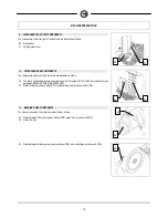
Page 24: ...n of the brush bristles during assembly the point of the brush viewed from the above should be towards the front of the machine 39 BRUSH HEAD EXTRA PRESSURE INNOVA 2011 65 75 85 B VERSIONS The pressur...

Page 25: ...on tank there is a suitable level indicator pipe 5 placed in front of the driver seat 43 KIT WATER MANAGEMENT INNOVA 2011 60 B VERSIONS If you want to increase the working capacity of the machine you...

Page 26: ...etting 8 The second screen visualises what battery technology has been set for machine operation in this case it s lead batteries to set another type of battery for instance gel contact the qualified...

Page 27: ...solution tank In extraordinary cases there is a mechanical device float on the lid that when the recovery tank is full shuts off the air to the suction motor intake TO protect it the sound of the vac...

Page 28: ...us solutions 7 Slide the suction tube 4 from the squeegee sleeve 8 Remove the squeegee 5 from the support arm by unscrewing the handwheel 6 9 Clean well both the squeegee and the rubbers with a jet of...

Page 29: ...ween the squeegee and the tank 4 Reposition the cap on the drainage tube and lower the suction cap To lock the prop 3 just slightly raise the cap release the prop 3 and lower the cap up to close it 48...

Page 30: ...implified by first loosening the handwheel 3 on the pin Then re tighten the handwheel 3 to block the squeegee in place 6 Finally insert the squeegee tube in the special sleeve ATTENTION Before perform...

Page 31: ...hthand lever 1 for the counter clockwise movement of the brush head ATTENTION Before performing any maintenance remove the keys from the panel and disconnect the battery connector of the machine WARNI...

Page 32: ...n the key to the OFF 0 position and remove it from the electrical board WARNING Before performing any maintenance remove the keys from the panel and disconnect the battery connector of the machine WAR...

Page 33: ...nter clockwise until the hopper locking lever allow its extraction 6 Using the flush handle 3 remove the hopper and empty it 7 Check the wear of the rubber 5 and clean it with a jet of water 8 Turn th...

Page 34: ...emove the keys from the panel and disconnect the battery connector of the machine WARNING This operation must be carried out using gloves to protect against contact with dangerous solutions 57 CLEANIN...

Page 35: ...gerous solutions 4 Remove the suction hose from the squeegee nozzle 5 Remove the suction hose from the waste collection tray 6 Make sure the recovery tank is empty otherwise empty it completely 7 Grip...

Page 36: ...eegee depending on the rubber see ADJUSTING THE HEIGHT OF THE SQUEEGEE SUPPORT 62 REPLACEMENT OF THE BRUSH HEAD CASING Periodically check the condition of the brush head casings that serve as protecti...

Page 37: ...he maximum position 12 Turn the detergent percentage adjustment knob 2 to the maximum position 13 Insert the battery connector into the machine connector 14 Place the main switch in position ON I 15 D...

Page 38: ...DOES NOT CLEAN WELL 1 Check the state of wear and tear of the brushes and if necessary replace them The brushes should be changed when the bristles are about 15mm long To replace them see REPLACING TH...

Page 39: ...rating function 4 Check no thermal protection device has intervened 5 Check the correct connection of the motor to the terminal under the footboards 71 IT IS IMPOSSIBLE TO RAISE OR LOWER THE BRUSH HEA...

Page 40: ...m is out of use To by pass the automatic water detergent dosing system you must rotate the tap lever 1 on the rear centre of the brush head downwards in this way you can go on working even with the sy...

Page 41: ...parate the following materials and send them to the appropriate collection centres in accordance with the environmental hygiene regulations currently in force brushes filter electric and electronic pa...

Page 42: ...rush tends to jump PAD HOLDER The pad holder is recommended for cleaning shiny surfaces There are two types of pad holder 1 the traditional pad holder is fitted with a series of anchor points that all...

Page 43: ...ds Immunity for industrial environments EN 61000 6 3 Electromagnetic compatibility EMC Part 6 3 Generic standards Standard emission for residential commercial and light industrial environments EN 6100...

Page 44: ...methodology EN 12100 2 Machine safety Fundamental concepts fundamental principles of design Part 2 Technical principles EN 61000 6 2 Electromagnetic compatibility EMC Part 6 2 Generic standards Immun...

Reviews: